 Control Surface Construction Techniques
Fabrication of a MIDI Control Surface requires many individual steps. A list of steps and their current status is tabulated below.
| Steps to Complete | ||
|---|---|---|
| Activity | Description | Status |
| Pre-Production | ||
| Develop Design | Select Components and Architecture | Complete |
| Acquire Parts | Controls, housing/hardware, electronics | Complete |
| Electronics Board | ||
| Power Supplies | +6VDC Motor, +5VDC Digital, +5VDC Analog | Complete |
| Motorized Pot Driver | Install IC's, heatsink, power rails | Complete |
| Analog Input Filters | Install R/C input filters | Complete |
| Analog Mux and Converter | Install and Connect 3 MAX1110s | Not Done |
| MIDI Interface | Install 2 opto's, connect to micro | Not Done |
| Port Extenders | Connect 74HC595 to Motor Drivers | Complete |
| Microcontroller | Install DS89C420 connect to periphs | Not Done |
| Machining | ||
| Housing | Drill for pots, punch for joysticks, route for LCD | Not Done |
| Cosmetic | Panel Design | Select place & legend | Not Done |
Here is a current scan of the board
Construction Technique
The control surface electronics mount on perfboard using point to point wiring. As this Midi Control Surface is both the first and final of it's kind, this technique is an agile design format as long as provision is made for "robust" construction. All components are through hole and the integration is pretty high for device of this type.
Sockets are used for major control components. This allows replacement for failed parts but also allows for any future "design tweaks" by socketed daughter electronics. Notably, the motor driver chips are not socketed. This is to allow for heat sinking the chips using PCB mounted copper strip.
Motor Driver Heatsink
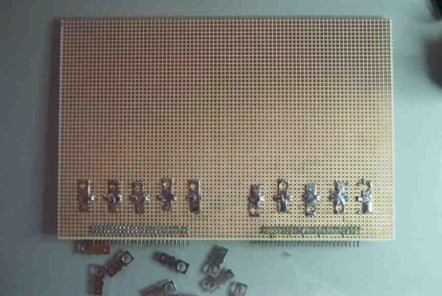 A simple PCB mounted heat-sink was made in order to keep the circuit board "profile" as "short" as possible. A #10 stud to tab metal adapter, soldered directly to the L293 ground pins, comprises the heat-sink. This method is depicted in the picture on the right. A larger picture can be viewed by "clicking" on the image.
Look and Feel
The LMB Keyboarder is a generally known off-the-shelf enclosure. The KB-20 model was chosen for use in this project. The 20 inches of length equals that of my MG-1. The 6.9 inch panel height is just enough to mount a large LCD and the numbers of controls required.
The 1 inch diameter "knobs" are intended to encourage their use and allow good precision for manual settings. The potentiometers are firm and sure when manually activated.
Presently i intend to use lacquer sealed adhesive Photo Silk Fabric for panel legending. I expect this to look very good if not commercial. This is suitable for InkJet printing and is intended for mouse pad, album covers or other "cloth" graphic uses.