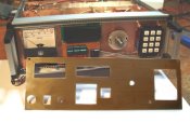
 ---- G4FEV----WINTER PROJECT 2008/09 ----
HF Transceiver
 Updated 20th Feb 2009.
 ---- G4FEV----WINTER PROJECT 2008/09 ----
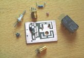 marked with an "A"
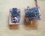
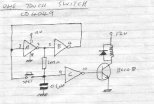 which is great for switching circuits using momentary action switches.
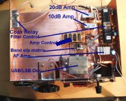 It's all looking a bit tatty at this stage but can be tidied up later when everything is in its right place. (In other words I'm just making it up as I go along !!!)
25th January
At last we have some RF output. ![]()
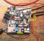 Here is the small power amplifier that runs 10 watts RF output from 1.8 - 30MHz.
Thanks to Jon
 ![]() GM4JTJ for the PA transistors and John
GM4JTJ for the PA transistors and John ![]() G4NPH for a valuable supply of 2N3866 driver transistors.
G4NPH for a valuable supply of 2N3866 driver transistors.
This small PA stage can actually manage 20 watts output BUT harmonics and other products make up half of the power when driven above the 10 watt setting.
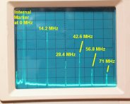 The RF output displayed on my homemade Spectrum Analyser.
The amplifier is set at 10 watts out at 14.2MHz, you can see the harmonic relationships.
The second harmonic at 28.4MHz is 20dB down (100mW).
3rd Harmonic at 42.6 is only 12dB down (650mW).
4th at 56.8 is 22dB down (64mW) and 6th at 71MHz is 24dB (40mW).
Clearly the next stage must be some Low-Pass-Filters before further amplification or use on the air can take place.
..............................................................
1st February
Here is the Low Pass Filter board.
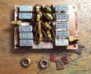 There are 5 LPF's. Individual ones for 160M, 80M & 40M. The filter for 30M, 20M & 17M is shared as is the filter for 15M, 12M and 10M. The components for 160 Metres are just about to installed. The Toroids came from the G-QRP Club sales (£1 for 5) and those nice relays from a local radio rally @ 50pence for the bag of ten. Wish I had some more ! The Silver Mica capacitors are salvaged from a PYE HF transceiver board, again from a rally at £1 for 2 boards.....Bargains...
Here is the plot of the filter for 30, 20 & 17M. The attenuation at 20.270MHz (10.135MHz x 2) was only around 10dB so a trap was fitted tuned to that frequency which explains the nice peak at 20.27MHz.
Loss at 28MHz is 25dB, 42MHz 45dB.
And the proof that it works.
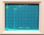 Compare this to last weeks plot shown above.
The second harmonic is now around 300 micro watts and the I had to overdrive the PA to get that much.........
..............................................
8th February.
Work on the rear panel has progressed this week.
The PA and LPF modules are in position.
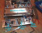
The power/SWR sensor will be wired to the front panel meter and will also feed the ALC module controlling the output power in the event of a high SWR.
..............................................
15th February.
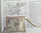 The ALC unit is a direct copy of the G3TSO circuit from the Rad Com handbook. It works extremely well reducing the transmitter output if the SWR increases and limiting the drive to the PA when a safe limit is reached. I am indebted, once again,
![]() to GM4JTJ for providing the IC for this circuit.
to GM4JTJ for providing the IC for this circuit.
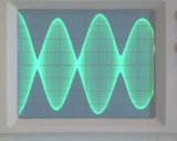 Here is the result of a 2 tone test with the PA running 10 watts output. Spectrum Lab software incorporates a 2 tone test facility and the result can be seen as nicely round topped modulation with sharp crossover points. I'm happy with that.
..........................
20th February.....
Just the front panel to complete and fit then we will be on the air!
