 ---- G4FEV----WINTER PROJECT 2008/09 ----
HF Transceiver

 ---- G4FEV----WINTER PROJECT 2008/09 ----
Introduction
Although I'm not really an HF band enthusiast (More UHF and microwave) the idea of building an all band HF transceiver has always appealed.
Those of us "of a certain age" will remember reading those articles in Practical Wireless and The Radio Constructor during the 70s & 80s by F.G. Rayer and Fred Judd detailing the superb construction of receivers and transmitters.
Making contacts around the world using equipment built on the kitchen table, mostly out of scrap or reclaimed parts (because it's cheaper that way) must be more satisfying than pressing the button on my other radios made in Japan.
So, The Winter 2008/9 project is a 9 band SSB HF transceiver. I will try and keep this online diary so you can watch my progress (or lack of it).
THE BIG PLAN (Design Goals)
* All 9 Amateur HF bands 160 to 10 metres
* Power output to be decided but probably between 20 & 100 watts
* A high performance receiver but without spending huge amounts of cash or going as far as DSP.
* In fact I would like to spend as little as possible using mostly reclaimed parts from the junk box.
My box of old PMRs, CBs and previously
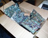 enjoyed projects that I plan to recycle.
Here's a block diagram of my original
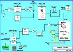 design plan.
As all the modules will be on plugs & sockets it will be easy to change things around and replace/improve sections when the time is right.
Perhaps a 10.7MHz IF will be too close when operating on the 10MHz band. The intention is to make my own crystal filter using crystals removed from 10.7MHz PMR filters. Replacement with a 9MHz crystal filter will be easy if one can be located at the right price. (i.e. £ nothing !)
Let's Go...October ....... DDS VFO (Direct Digital Synthesis)
The original idea was to build the Pic-n-Mix DDS VFO by G3XJP as published in Rad-Com (Jan 1999) but unfortunately he refused to send me the necessary hex file to program the pic stating that "it was an obsolete and no longer supported project" and added that I should not contact him again. Ho Hum !
I analysed various DDS designs and found this superb effort by VU3CNS.
http://www.hamradioindia.org/circuits/dds.php
It should be available here :
http://www.hamradioindia.org/downloads.php?d_op=viewdownload&cid=3
This is a truly inspired piece of work with, outputs for band and mode switching, 2 x VFOs, 20 memories, keypad frequency entry, + or - IF offset, RIT and much more. In fact everything you could want for an HF controller.
Most amateur DDS VFOs are based on the Analogue Devices AD9851. Thanks to the enlightened policy of the manufacturer, Analogue Devices will send you a free sample for experimentation purposes. http://www.analog.com
This DDS system is also well worth considering. http://groups.yahoo.com/group/dds_vfo
October 2008
The AD9851 mounted on a 28 Pin IC holder. (The chip is under the horizontal copper strip!)
 Working lash-up of the complete VU3CNS DDS system
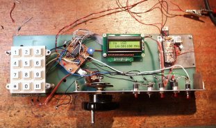 Instead of an expensive Rotary Shaft Encoder for the main tuning control the "scroll wheel" encoder was cut from a scrap computer mouse. It works fine and cost nothing. It has been temporarily mounted on the back of an old potentiometer.
The 16 x 2 Display was salvaged from an old Eltek alarm module (Thanks John G4NPH) and the keypad removed from an old phone.
You are probably seeing an underlying tone here that most of the things I'm doing cost nothing.
The less I spend on a project the greater the achievement (Also, of course, I'm a cheapskate).
Total cost so far....
PIC16F628 x 2 free samples from Microchip
AD9851 free sample from Analogue Devices
£ Absolutely Zero ![]()
Next will be the SSB Generator and IF AF stages.......Stay tuned.
-----------------------------------------------------------------------------------------
27th October.
An interesting day working on a homemade crystal filter. I would prefer a 9MHz IF but, until suitable crystals or even a commercial filter, complete with its USB & LSB crystals, can be found I am stuck with the junk box solution.
After dismantling some 10.7 MHz filters from old PMR 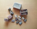 rigs and selecting identical crystals.
I downloaded AADE Filter-Design-Program to calculate 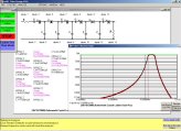 the tuning capacitors.
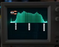 The result is an acceptable 6 pole SSB crystal filter. The response displayed on the scope while sweeping with John's signal generator showing about 2.5KHz bandwidth, reasonably symetrical and flat top (ripple)
I'm happy with that.
30th October.
Now for some real building. The Belthorn SSB IF stage is a nice compact design with the following features. Local oscilator, complete IF stage, SSB mixer/Balance Modulator, AF Amp, AGC & Final mixer.
Described in Rad-Com May 2000 (In the good old days when it had proper radio articles !) and also here:- http://www.g4gxo.cwc.net/belthorn_ssb_if_module.htm
Masking up the copper board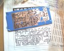 ready for the etching bath.
The board etched and drilled 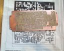 ready for some components.
The weekend should see the board finished and working with any luck.
...........................................................
9th November.
The IF board is finished but not without a struggle........
First, there are a few mistakes in the Rad-Com article and an error on the PCB layout. (These are fixed on the Belthorn web site by the way) These errors took a while to find in addition to the following bugs..........
The LM386 audio amp. I have always found the performance of this audio amp to be disappointing and sure enough it was "hissy" with a tendency to take off, sounding more like an outboard motor. The LM386 was removed from the board and a better audio stage will be constructed on its own board later.
Next.... 10.7MHz carrier leakage appearing on the SSB output.... It was probably acceptable but I wanted better. To cure this the 10.7MHz oscillator was stripped from the board and built "ugly style" in a tinplate box. This also gave the opportunity to build both USB and LSB oscillators together. Result... All signs of the 10.7 carrier have gone.
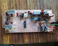 Here's the board part completed. You can already see my attempts at screening the 10.7MHz oscillator at the top right of the board before giving up completely and building it separately.
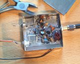
![]() Thanks to GM4JTJ for the 10.70125MHz crystal.
Thanks to GM4JTJ for the 10.70125MHz crystal.
Results... The PCB track side of the board now looks a bit of a mess after all the modifications (so I'm not going to show it to you!) but it works an absolute treat.I should really strip the board and rebuild a neater version but it's working so well I will leave that for a later date. All the components have been stripped and recovered from old boards including the expensive mixers (SRA-1 and SRA-1H are £10 - £20 each. If you want one for your own project let me know.) so we are still at £ zero.
Right folks ...That's it for another week. Next I had better rebuild the VU3CNS DDS system you saw at the top of the page into its full and final version but stand firm as I will be spending some money !!! ........................................................... 16th November Pesky PIC Programming Problems! There are two PIC (Peripheral Interface Controller) microcontrollers in the VU3CNS DDS system.
One talks to the DDS chip and the display, the second is for band-switching and mode outputs. PIC1 had already been programmed for the early DDS lash-up you saw at the top of the page. PIC2 failed to load its HEX file when using my home-made PMPIC (Poor-Mans-PIC-blower).
Is the PIC faulty? Is the HEX file faulty? I tried erasing & programming PIC1 again and that failed also.....Now I have nothing......damn!
After several cups of tea and a few hours "fafing around" another (free of course) PIC blower program was downloaded from Oshon Software. After an hour building the programming board, hey presto, .... both PICs programmed without any further problems.![]() What should have been a 5 minute job took all day.....
What should have been a 5 minute job took all day.....
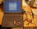
The DDS control encoder has been assembled (What would have been called "The VFO" in the old days.)
If you have ever tuned Eddystone or Racal equipment then you will know how a nice VFO should feel.
Components ready for assembly. 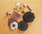 You can see the outer knob, bearing carrier, flywheel and the tiny encoder cut from an old PC mouse.
That's all the progress for this week but some money has been "invested".
A larger LCD display for the front panel (Justified by my dodgy eyesight). £13.00 Better quality and easier to mount front panel keypad. £3.00 Some double sided PCB from ebay for the chassis. £10.00 Total cost so far £26.00
Next week.... More work on the DDS output level and filtering. How is all this lot going to fit together? ....................................................
21st November............ The mixer is a Mini-Circuits SRA-1H which should make a virtually bombproof front end however, it requires a huge amount of local oscillator drive (+17dBm or 50 mW). Obtaining this sort of power should be relatively easy but acheiving a flat output of +17dBm over the entire spectrum is proving a little difficult.
With a 10.7 MHz IF the local oscillator will run from 12.5MHz to 40.3 MHz (That's 1.8MHz +10.7 and 29.6MHz +10.7).
After a period of empirical development (empirical denotes: information gained by means of observation, experience, or experiment) In other words I fiddled around with the amplifier stage for a few hours until it worked correctly.
The end product uses 2 tiny MAR-3 mimic amplifiers within the DDS compartment and a separate 2N3866 amplifier in a small box made from PCB offcuts.
Here is the DDS compartment 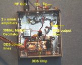 with its filter and 2 mimic amplifiers which produce a reasonably flat output of +5dBm over the required spectrum.
2N3866 amplifier stage 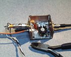 Boosting the ouput to the required +17dBm. The device on the left is a 50 ohm diode probe power monitor.
This is an extra DDS filter 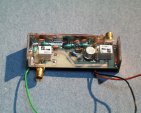 switched in on the 17m 15m 12m & 10m bands.
Next Stage....Now I have all these boards scattered over the bench, connected up in a precarious fashion, it's time to build the chassis.
The internal layout will look something like this. 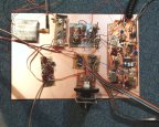
........................................................ 30th November. A rather lazy week here with little progress. The various boards are joined together on the bench with, hurriedly thrown together, bandpass filters for 80 and 160 metres and most evenings have been spent listening. (Goodness, some people do talk rubbish !)
Listening on the bands is something I haven't done for years.
There is certainly an added thrill using home-made stuff.
Boards accidentaly touching together have caused one or two rather alarming sparks ! This has prompted some work on the chassis which is made from double sided PCB material.
You can obtain blank FR4 PCB material from Lamar Group on ebay http://stores.ebay.co.uk/PCB-Consumable-Supplies
The chassis, cut and ready for assembly. 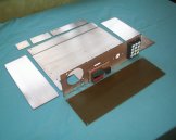 Accurate measuring is not my strong point.
A quick dab with the soldering iron
 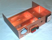 and here's the result.
![]() G0PYS very kindly gave me a flat-pack RS case
G0PYS very kindly gave me a flat-pack RS case 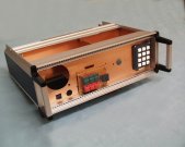 which has been cut-&-shut to fit.
Results so far look promising with pleasing receiver performance.
Next, some of the boards will be mounted on the chassis...73 for now.....
........................................................
7th December.
Once again I have spent far too much time listening when I should be building.
Time to start some serious front-end filtering.
We want to limit those huge out of band broadcast stations from swamping the mixer and remove the image frequency.
Before constructing the filters an accurate inductance meter was constructed and calibrated.
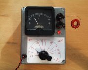 This is accurate to within 0.5uH.
9 filters are required, one for each band. They are built on small scraps of circuit board for initial testing. 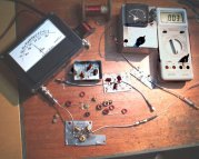 Seen here with my homemade dBm meter.
Here you can see the 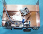 PIC controllers mounted in the chassis with the DDS board resting on top.
Front view 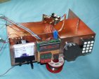
Next week I should have all the filters installed on the chassis. .....................................................
14th December........
Next week I should have all the filters installed on the chassis.
Fat chance ! Achieving the desired performance is proving difficult.
I am finding the measured spec is often far away from the specified values with higher "in-band" loss and less attenuation out of band.
I have resolved to design & adjust my own until I find the desired performance.
In the meantime, the DC switching for the RF filters has been constructed as shown here.
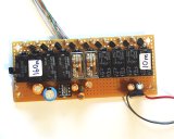
A bit of a hotch potch of relays but they are all I had in the junk box. Note that these relays only switch DC and not RF.
The small IC is a negative voltage generator for the -5V required by the RF switches.
I received a question...."What do all the switches do?"
Some of the switches have a dual purpose like most modern rigs. Press & hold for the second function which is part of the excellent VU3CNS DDS VFO design.
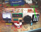 The VFO Step Size button is conveniently placed for pressing by the thumb while the VFO knob is rotated so setting the desired tuning rate with one hand.
Finally, this week, a top view of progress so far 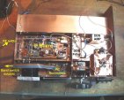
.................................................
21st December......
Good progress this week on the filter block.
The input and output switching for each filter is performed using SW-259 RF switches cut from old mobile-phone base station PCB's.
These miniature solid state coax switches, made by M/A COM, are excellent and very versatile devices (and of course I have plenty of them so they are free) !!!
SW-259 Spec... DC to 2.5GHz... Insertion loss 0.8dB... Isolation 55dB... 3rd order intercept +46dBm.. Switched using -5 Volts DC.
Here you can see the original circuit boards. 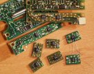 and a few switches cut out ready to install. This method may seem rather crude but it works fantastically well.
This image shows the filter block, once again, made from pcb. 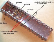 The feed-throughs along the top feed the -5volt DC switching voltage. Filters for 160m, 80m, 40m and 30m have been installed and tested.
Another view showing the output RF switching SW-259 PCBs. 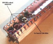 The input switching pcb is mounted on the side nearest the camera.
RF input/output runs in screened channels under the board. 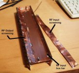 In this view (showing the underside of the filter block) I am just about to solder the screening in place for the input side.
............................................
 28th December......
Despite all the food, drink & other festivities time was found to complete the filter bank and mount it on the chassis.
Here we see the completed filter block 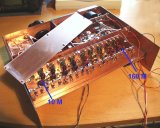 A really bad design on my part as I made the sides far too deep and it was difficult to work inside.
Top view, note the pcb lid 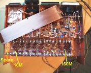 which should keep any unwanted RF out of the box. It is held in place by 5mm nuts soldered to the pcb edges.
The position marked as "spare" is for a general coverage filter automatically switched in when outside of an amateur band. I plan to install a filter for the 5MHz band here.
The toroid cores obtained from the G-QRP club sales. approx £5.
...........................................