24) The "Lighthouse" Fire Control Tower at Breezy Point
Updated: June 29, 2005 (Spelling corrections)
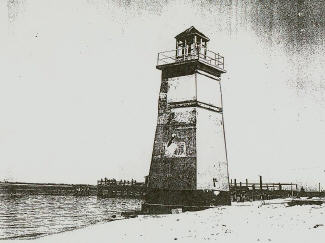
The "Lighthouse" Fire Control Tower at Breezy Point, NY
Photo Bill Curtis - 1953
Note the topside wooden structure.
This fire control tower was constructed during World War II (completed 7/15/43) to serve as the secondary base end (B") station for both Battery Kessler and Battery Fergusson. It was disguised to look like a lighthouse by the addition of a wood structure with windows on to of the tower. It contained 6 pedestal mounts for azimuth instruments, and was later used
as the primary base end and spotting (B1S1) station for Battery Kessler, the fourth and the fourth base end and spotting (B4S4) station for Battery 218 at Fort Wadsworth, Staten Island, NY, and the third spotting station (M3) for the minefields of the East side of the Ambrose Channel.
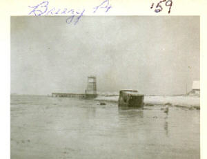
The Cable Hut at Breezy Point Photo: Bill Curtis - 1959
Residents of Breezy Point still refer to this structure as the "Lighthouse". It is located on the bay side of Breezy Point in Rockaway, NY, at approximately Beach 218th Street. An inspection of the structure in July 1999 revealed that it is impossible to enter inside the tower due to the doorway being completely cemented over.
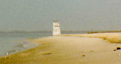
The "Lighthouse" Fire Control Tower at Breezy Point, NY Photo: Private Collection - 1999
This tower is now listing to one side due to the erosion of sand from under it's base. Historic research concerning the history of this tower is underway. If you are interested in helping with the research on this important landmark in Breezy Point, or have any old photos or maps showing the tower, please contact us.
How did all of this work?
This tower was part of a visual fire control system used to direct coastal guns. Many such towers were constructed during World war 2 in the NY-NJ area. In 1944, the guns of Battery Harris were directed by seven base end stations, ten spotting stations, and eight radar towers. The "Time Interval" system was used to facilitate firing at moving targets.
The following explanation of the Time-Interval (TI) system is provided from the "ROTC Manual - Coast Artillery - Basic", 10th Edition (1938), The Telegraph Press, Harrisburg, Pa, page 127-128:
"In each station there is a bell forming a part of the time-interval system. This system rings all bells simultaneously at the prescribed time interval, usually 30 seconds, thus indicating to observers the exact instant at which
an observation is to be made.
When the time-interval (TI) bell rings, the observers stop following the target for an instant and the reader in each station reads from the instrument the azimuth of the target (and its range if vertical base is being used).
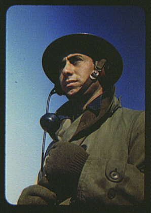
Man of the Fort Story, Va., Coastal Defense
Photographer: Alfred T. Palmer
Date: March 1942
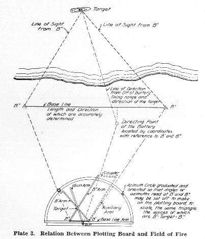
Each reader is equipped with a telephone headset connecting him directly with the arm setter in the plotting room who operates the arm of the plotting board representing the line of sight of the station from which the readings are being received.
The edge of the plotting board is graduated in terms of angular measure and is oriented in such a manner that when each of the two arms is set at the azimuth reported by the reader at the corresponding station, the arms will represent the lines
of sight of the respective instruments at the instant the observations were made.
Since observations are made simultaneously at both base-end stations, when the arms are set at the azimuths received from the stations, their intersection will mark the position of the target at the instant of observation. This point is marked by the plotter upon the plotting board. The operation is repeated for each time interval, successive positions of the target being determined."
These plotted positions will be used to calculate a future "Predicted Point" for the target and then a "Set Forward" point corrected for the distance the target will travel during the time of the flight of the projectile. This point is used to determine the azimuth and elevation to be provided to the gun crews. Upon the next ringing of the TI bell, the gun crew will fire the gun.
This system is accurate providing that the ship does not alter its speed or direction and a reasonable number of points are usually plotted before a "Set Forward" point is calculated.
Findings of Board of Officers
Establishment of Points
Fort Tilden, N.Y.
Note #1 - Point "A", Original proposed location of Control Tower (M4)
Note #2 - Point "B", Triangulation Seawall (USCA) 1940, and Original Proposed Location for Searchlight #8
Note #3 - Point "C", Final Selected Point for Casemate
Note #4 - Point "D", Final Selected Site for Cable Hut #3
Note #5 - Point "E", Final Selected Site for Cable Hut #4
Note #6 - Point "F", Final Selected Site for Searchlight #8 (See Note #2) (Must be Accurately Located by Survey)
Note #7 - Point "G", Final Selected Site for Control Tower M4, B"
Kessler, & B" Fergusson (To Be Erected Over Cable Hut #4)
Note #8 M4-M5 Base Line
Note #9 M5 to be Located in New Deck on Tower "A"
Note #10 Submarine Cable 25 Pr
Legend:
_.._ Submarine Cable
_._ Land Cable
--- Base Line
Dated 4-19-41
Originally classified as SECRET, Declassified in accordance with E.O. 12958, by: DMJ - National Archives and Records Section, Date
3/11/99
Explanation of terminology used on this map:
Searchlight #8 is probably a 60-inch searchlight used to
illuminate targets for identification and fire control purposes. This searchlight would require a power generator to be located nearby.
The exact function and purpose of the referenced Casemate is presently unknown. A survey of existing structures in the are needs to be undertaken.
Cable Hut #3 is located just west of the current tower. The cables lead from this hut to the casemate. These cable huts usually contained junction boxes with rows of screws to connect the cable ends.
Cable Hut #4 may still exist, but the current tower was built over this hut. This cable hut connected the 25 pair (50 conductor) cable from Fort Tilden to the casemate
Control Tower M4 is the designation for the current tower which stands in Breezy Point today.
B" Kessler is the secondary observing station for Battery Kessler, a pair of 6-inch M1900 Rapid Fire rifled guns installed at Fort Tilden.
B" Fergusson is the secondary observing station for Battery Fergusson, another pair of 6-inch M1900 Rapid Fire rifled guns installed at Fort Tilden.
The M4-M5 Base Line is the imaginary base line that connects the M4 Tower in Breezy Point to M5 to be located on the new deck of Tower "A", the 100 foot tall tower located at the western end of Fort Tilden. This tower was already in use as one of the base end stations for Battery Harris, the twin 16-inch
Model M1919 gun battery, so an additional deck was to be constructed atop the existing structure.
The Submarine Cable 25 Pr is a 25 pair (50 conductor) cable that was laid along the floor of the bay to connect the M4 Tower and casemate to the protected Switchboard (SWB) and plotting room in Fort Tilden. This cable was used for voice telephone communications and bell signals used for time intervals for azimuth reading and plotting.
Please contact us if you were stationed at Fort Tilden and served in this fire control tower.