The nickel tour continued... |
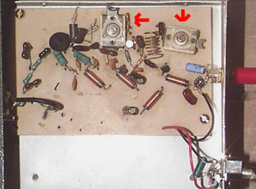 |
A closer look at the transmitter.
Yes, it's the famous 3-transistor bug your mother warned you
about. When I built this in 1993 there was no internet to consult
for technical knowledge, and yet it's served me well for
a decade. The secret to keeping the frequency tolerance to ±10kHz
are the two variable compression capacitors (arrows) trimming
the oscillator tank and output. Tuning adjustments as delicate
as ±1kHz can be made with these trimmers. Output is 2.5
Vrms, which delivers about 100 milliwatts to the antenna. |
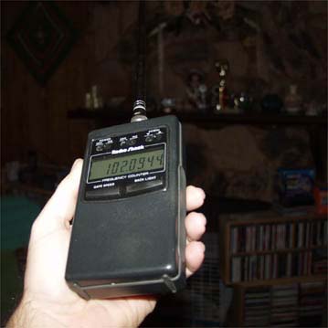 |
Because I didn't have AFC on
this old transmitter, it was critical to monitor the oscillator's
stability. Here is my hand-held Radio Shack frequency counter (no longer available)
that helped me to stay somewhat in-channel. It cannot be coupled
directly to the transmitter, so I had to find hot spots near
it or under the antenna with enough signal strength to trigger
a reading. The display in this picture shows I'm in a spot that
produced a semi-accurate reading, so it's helpful to corroborate
your measurement with a digital FM receiver. |