EE 526
Satellite Communication
Prepared by
Farid Bouges Bandar Saman
Supervised By
Prof. Adnan Afandi
INTRODUCTION
In the early 1960s, the American Telephone and Telegraph Company (AT&T) released studies indicating that a few powerful satellites of advanced design, could handle more traffic than the entire AT&T long-Distance communications network. The cost of these satellites was estimated to be only a fraction of the cost of equivalent terrestrial microwave facilities. Unfortunately, because AT&T was a utility, government regulations prevented them from developing the satellite systems. Smaller and much less lucrative corporations were left to develop the satellite system, and AT&T continued to invest billions of dollars each year in conventional terrestrial microwave system Because of this, early developments in satellite: technology were slow in coming.
Throughout the years the prices of most goods and services have increased substantially; however, satellite communications services have become more afforuble each year. In most instances, satellite systems offer more flexibility than submarine cables, buried underground cables, line-of-sight microwave radio, troposphenc sealer radio, or optical fiber systems.
Essentially, a satellite is a radio repeater in the sky (transponser).
A satellite system consists of :
1. Transponder
2. Ground-based station to control its operation
3. User network of earth station that provide the facilities for transmission and reception of communications traffic through the satellite system.
Satellite transmissions are categorized as either bus or payload. The bus includes control mechanisms that support the payload operation. The payload is the actual user information that is conveyed through the system. Although in recent years new data services and television broadcasting are more and more in demand, the transmission of conventional speech telephone signals in analog or digital form) is still the bulk of the satellite payload.
HISTORY OF SATELLITES
The simplest type of satellite is a passive reflector, a device that simply "bounce" a signal from one place to another. The moon is a natural satellite of the earth and, consequently, in the late 1940s and early 1950s, became the first satellite transponder. In 1954 the U.S. Navy successfully transmitted the first messages over this earth-to-moon-to-earth relay. In 1956, a relay service was established between Washington, D.C. and Hawaii and, until 1962 offered reliable long-distance communications. Service was limited only by the availability of the moon.
In 1957 Russia launched Spuituk 1, the first active earth satellite. An active satellite is capable of receiving, amplifying, and retransmitting information to and from earth stations. Sputnik I transmitted telemetry information for 21 days. Later in the same year, the United States launched Explorer 1, which transmitted telemetry information for nearly 5 months.
In 1958 NASA launched Score, a 150-pound conical-shaped projectory. With an on-board tape recording, Score rebroadcasted President Eisenhower's 195S Christians message. Score wls the first artificial satellite used for relaying terrestrial communications. Score was a delayed repeater satellite; it received transmissions from earth stations, stored them on magnetic tape, and rebroadcasted them to ground stations farther along its orbit.
In 1960 NASA in conjunction with Bell Telephone Laboratories and the Jet Propulsion Laboratory launched Echo, 2 100-ft-diameter plastic balloon with an aluminum coating. Echo passively reflected radio signals from a large earth antenna. Echo was simple and reliable but required extremely high power transmitters at the earth stations. The first transatlantic transmission using a satellite transponder was accomplished using Echo. Also in 1960, the Department of Defense launched Courier. Courier transmitted 3 W 01" power and lasted only 17 days.
In 1962, AT&T launched Telstar I. the first satellite to receive and transmit simultaneously. The electronic equipment in Telstaf I was damaged by radiation from the newly discovered Van Alien belts and, consequently, lasted only a few weeks Telsur II was electronically identical to Telstar I, but it was made more radiation resistant. Tehiar II was successfully launched in 1963. It was used for telephone, television, facsimile, and data transmissions. The first successful transatlantic transmission of video was accomplished with Telstar II.
Early satellites were both of the passive and active type. Again, a passive satellite is one that simply reflects a signal back to earth; there are no gain devices on board to amplify or repeat the signal. An active satellite is one that electronically repeats a signal back to earth (i.e., receives, amplifies, and retransmits the signal). An advantage of passive satellites is that they do not require sophisticated electronic equipment on board, although they are not necessarily void of power. Some passive satellites require a radio beacon transmitter for tracking and ranging purposes. A beacon is a continuously transmitted unmodulated carrier that an earth station can lock onto and use to align its antennas or to determine the exact location of the satellite. A disadvantage of passive satellites is their inefficient use of transmitted power. With Echo, for example, only 1 part in every 1018 of the earth station transmitted power was actually returned to the earth station receiving antenna.
ORBITAL SATELLITES
The satellites mentioned thus far are of the orbital or nonsynchronous type. That is, they rotate around the earth in a low-altitude elliptical or circular pattern with an angular velocity greater than (prograde) or less than (retrograde) that of Earth. Consequently, they are continuously gaming or falling back on Earth and do not remain stationary to any particular point on Earth. Thus they have to be used when available, which may be as short a period of time as 15 minutes per orbit. Another disadvantage of orbital satellites is the need for complicated, and expensive tracking equipment at the earth stations. Each Earth station must locate the satellite as it comes into view on each orbit and then lock its antenna onto the satellite and track it as it passes overhead. A major advantage of orbital satellites is that propulsion rockets are not required on board the satellites to keep them in their respective orbits.
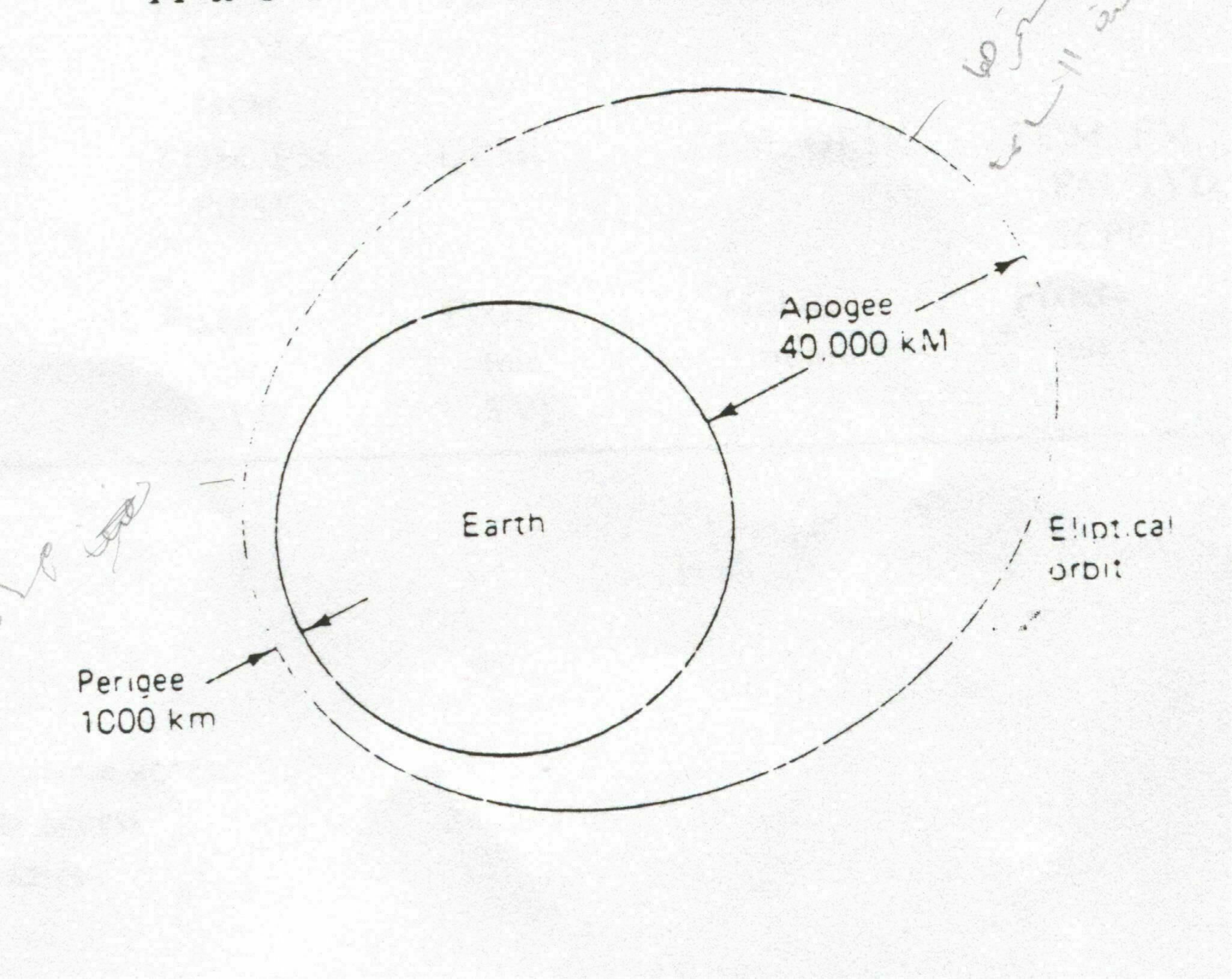
One of the more interesting orbital satellite systems is the Soviet Moiniya system. It is presently the only nonsynchronous-orbit commercial satellite system in use. Moiniya uses a highly elliptical orbit with apogee at about 40.000 km and perigee at about 1000 km (see figure 1). The apogee is the maximum distance from earth a satellite orbit reaches; the perigee is the minimum distance. With the Molniya system, the apogee is reached while over the northern hemisphere and the perigee while over the southern hemisphere. The size of the ellipse was chosen to make its period exactly one-half of a sidereal day (the time it takes the earth to rotate back to the same constellation). Because of its unique orbital pattern, the Molniya satellite is synchronous with the rotation of the earth. During us 12-h orbit, it spends about 11 h over the north hemisphere.
GEOSTATIONARY SATELLITES
Geostationary or geosynchronous satellites are satellites that orbit in a circular pattern with an angular velocity equal to that of Earth. Consequently, they remain in a fixed position in respect to a given point on Earth. An obvious advantage is they are available to all the earth stations within their shadow 100% of the time. The shadow of a satellite includes all earth stations that have a line-of-sight path to it and lie within the radiation pattern of the satellite's antennas. An obvious disadvantage is they require sophisticated and heavy propulsion devices on board to keep them in a fixed orbit. The orbital time of a geosynchronous satellite is 24 h, the same as Earth.
CURRENT SATELLITE COMMUNICATIONS SYSTEMS
|
Characteristic System
|
|||||
|
|
Westar
|
Intelsat V'
|
SBS
|
Fleet-satcom
|
Anik D
|
|
Operator
|
Western Union Telegraph
|
Intelsat
|
Satellne Business Systems
|
U.S. Dept. of Defense
|
Telsat Canada
|
|
Frequency
|
C
|
C and Ku
|
Ku
|
UHF. X
|
C. Ku
|
|
Band
|
|
|
|
|
|
|
Coverage
|
Consus
|
Global.
|
Consus
|
Global
|
Canada.
|
|
|
|
zonal.
|
|
|
northern
|
|
|
|
Spot
|
|
|
U.S.
|
|
Number of
|
12
|
21
|
10
|
12
|
24
|
|
Transponders
|
|
|
|
|
|
|
Transponder BW (MHz)
|
36
|
36-77
|
43
|
0.005-0.5
|
36
|
|
EIRP (dBu)
|
33
|
23 5-29
|
40-43 7
|
26-28
|
36
|
|
Multiple
|
FDMA.
|
FDMA.
|
TDMA
|
FDMA
|
FMDA
|
|
Access
|
TDMA
|
TDMA.
|
|
|
|
|
|
|
reuse
|
|
|
|
|
Modulation
|
FM. QPSK
|
FDM FM. QPSK
|
QPSK
|
FM. QPSK
|
FDM. FM. FM/TVD, SCPC
|
|
Service
|
Fixed
|
Fixed
|
Fixed
|
Mobile
|
Fixed
|
|
|
teie.
|
tele.
|
tele.
|
military
|
tele
|
|
|
TTY
|
TVD
|
TVD
|
|
|
C-band- 34-6.425 GHz
Ku-band 10.95-14.5 GHz
X-band: 7.25-8 4 GHz
TTY teletype
TVD TV distribution
FDMA frequency-division multiple access
TDMA time-division multiple access
Consus continental United Slates
Syncom I, launched in February 1963. was the first attempt to place a geosynchronous satellite into orbit. Syncom I was lost during orbit injection. Syncom II and Syncom III were successffully launched in February 1963 and August 1964, respectively. The Syncom III satellite was used to broadcast the 1964 Olympic Games from Tokyo. The Syncom projects demonstrated the feasibility of using geosynchronous satellites.
Since the Syncom projects, a number of nations and pprivate corporations have successfully launched
satellites that are currently being used to provide national as well as regional and international global communications. There are moore than 80 satellite communications systems operating in
the world today. They provide worldwide fixed common-carrier telephone and data circuits: point-to-point
cable television (CATV); network television
distribution; music broadcasting; mobile
ORBITAL PATTERNS
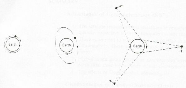
Once projected, a satellite remains in orbit because the centrifugal force caused by its rotation around the earth is counterbalanced by the earth's gravitational pull. The closer to earth the satellite rotates, the greater the gravitational pull and the greater the velocity required to keep it from being pulled to earth. Low-altitude satellites that orbit close to Earth (100 to 300 miles in height) travel at approximately 17,500 miles per hour. At this speed, it takes approximately 1.5 h to rotate around the entire earth. Consequently1, the time that the satellite is in line of sight of a particular earth station is only 1/4 h or less per orbit.
Medium-altitude satellites (6000 to 12,000 miles in height) have a rotation period of 5 to 12 h and remain in line of sight of a particular earth station for 2 to 4 h per orbit.
High-altitude, geosynchronous satellites (19,000 to 25.000 miles in height) travel at approximately 6879 miles per hour and have a rotation period of 224 h, exactly the same as the earth. Consequently, they remain in a fixed position in respect to a given earth station and have a 24-h availability time. F shows a low-, medium-, and high-altitude satellite orbit It can be seen that three equally spaced, high-altitude geosynchronous satellites rotating around the earth above the equator can cover the entire earth except for the unpopulated areas of the north and south poles.
Figure 2 shows the three paths that a satellite may take as it rotates around the earth. When the satellite rotates in an orbit above the equator, it is called an equatorial orbit. When the satellite rotates in an orbit that takes it over the north and south poles, it is called a polar orbit. Any other orbital path is called an inclined orbit.
It is interesting to note that 100% of the earth's surface can be covered with a single satellite in a polar orbit. The satellite is rotating around the earth in a longitudinal orbit while the earth is rotating on a latitudinal axis. Consequently, the satellite's radiation pattern is a diagonal spiral around the earth which somewhat resembles a barber pole. As a result, every location on earth lies within the radiation pattern of the satellite twice each day.
SUMMARY
Advantages of Geosynchronous Orbits
1. The satellite remains almost stationary in respect to a given earth station. Consequently, expensive tracking equipment is not required at the earth stations.
2. There is no need to switch from one satellite to another as they orbit overhead. Consequently, there are no breaks in transmission because of the switching times.
3. High-altitude geosynchronous satellites can cover a much larger area of the earth than their low-altitude orbital counterparts.
4. The effects of Doppler shift are negligible.
Disadvantages of Geosynchronous Orbits
1. The higher altitudes of geosynchronous satellites introduce much longer propagation times. The round-trip propagation delay between two earth stations through a geosynchronous satellite is 500 to 600 ms.
2. Geosynchronous satellites require higher transmit powers and more sensitive receivers because of the longer distances and greater path losses.
3. High-precision spacemanship is required to place a geosynchronous: satellite into orbit and to keep it there. Also, propulsion engines are required on board the satellites to keep them in their respective orbits.
LOOK ANGLES
To orient an antenna toward a satellite, it is necessary to know the elevation angle and azimuth (see Figure 3). These are called the look angles.
Angle of Elevation
The angle of elevation is the angle formed
between the plane of a wave radiated from an earth station antenna and the
horizon, or the angle subtended at the earth, station antenna between the
satellite and the earth's horizon. The smaller the angle of elevation, the
greater the distance a propagated wave must pass through the earth's
atmosphere. As with any wave propagated through the earth's atmosphere, it
suffers absorption and may also be severely contaminated by noise.
Consequently, if the angle of elevation is too small and the distance the wave
is within the earth's atmosphere is too long, the wave may deteriorate to a
degree that it provides inadequate transmission. Generally, 5° is considered
as the minimum acceptable angle of elevation. Figure 8-5 shows how the angle of
elevation affects the signal strength of a propagated wave due to normal
atmospheric absorption, absorption due to thick fog. and absorption due to a
heavy rain. It can be seen that the 14/12-GHz band is more severely affected than the
6/4-GHz band. This is due to the
smaller wavelengths associated with the higher frequencies. Also, at elevation
angles less than ![]() , the attenuation increases rapidly
, the attenuation increases rapidly
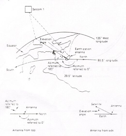
Azimuth
Azimuth is defined as the horizontal pointing angle of an antenna. It is measured in a clockwise direction in degrees from true north. The angle of elevation and the azimuth both depend on the latitude of the earth station and the longitude of both the earth station and the orbiting satellite.
LONGITUDINAL POSITION OF SEVERAL CURRENT SYNCHRONOUS SATELLITES PARKED IN AN EQUATORIAL ARC"
|
Satellite |
Longitude (oW |
Anik 1 |
104 |
|
Anik 2 |
109 |
|
Anik 3 |
114 |
|
Westar I |
99 |
|
Wcstar 11 |
123.5 |
|
Westar III |
91 |
|
Satcom 1 |
135 |
|
Satcom 2 |
119 |
|
Comstar D2 |
95 |
|
Palapa 1 |
277 |
|
Pah pa 2 |
283 |
ORBITAL SPACING AND FREQUENCY ALLOCATION
Geosynchronous satellites must share a limited space and frequency spectrum within a given arc of a geostationary orbit. Satellites operating at or near the same frequency must be sufficiently separated in space to avoid interfering with each other (Figure 4). There is a realistic limit to the number of satellite structures that can be stationed (parked) within a given area in space. The required spatial separation is dependent on the following variables:
1. Beamwidths and sidelobe radiation of both the earth station and satellite antennas
2. RF carrier frequency
3. Encoding or modulation technique used
4. Acceptable limits of interference
5. Transmit carrier power
Generally, 3° to 6° of spatial separation is required depending on the variables stated above.
The most common carrier frequencies used for satellite communications are the 6/4- and 14/12-GHz bands. The first number is the up-link (earth station-to-transponder) frequency, and the second number is the down-link (transponder-to earth station) frequency. Different up-link and down-link frequencies are used to prevent ringaround from occurring. The higher the carrier frequency the smaller the diameter required of an antenna for a given gain. Most domestic satellites use the 6/4-GHz band. Unfortunately, thus band is also used extensively for terrestrial microwave systems. Care must be taken when designing a satellite network to avoid interference from or interference with established microwave links.
Certain positions in the geosynchronous orbit are in higher demand than the others. For example, the mid-Atlantic position which is used to interconnect North America and Europe is in exceptionally high demand. The mid-Pacific position is another.
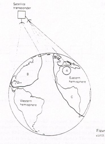
RADIATION PATTERNS: FOOTPRINTS
The area of the earth covered by a satellite depends on the location of the satellite in its geosynchronous orbit, its carrier frequency, and the gain of its antennas. Satellite engineers select the antenna and carrier frequency for a particular spacecraft to concentrate the limited transmitted power on a specific area of the earth's surface. The geographical representation of a satellite antenna's radiation pattern is called a footprint . The contour lines represent limits of equal receive power density.
The radiation pattern from a satellite antenna may be categorized as either spot, zonal, or earth (see Figure 4). The radiation patterns of earth coverage antennas have a beamwidth of approximately 17° and include coverage of approximately one-third of the earth's surface. Zonal coverage includes an area less than one-third of the earth's surface. Spot beams concentrate the radiated power in a very small geographic area.
Reuse
When an allocated frequency band is filled, additional capacity can be achieved by reuse of the frequency spectrum. By increasing the size of an antenna (i.e.. increasing the antenna gain) the beamwidth of the antenna is also reduced. Thus different beams of the same frequency can be directed to different geographical areas of the earth. This is called frequency reuse. Another method of frequency reuse is to use dual polarization. Different information signals can be transmitted to different earth station receivers using the same band of frequencies simply by orienting their electromagnetic polarizations in an orthogonal manner (90° out of phase). Dual polarization is less effective because the earth's atmosphere has a tendency to reorient or repolarize an electromagnetic wave as it passes through. Reuse is simply another way to increase the capacity of a limited bandwidth.
SATELLITE SYSTEM LINK MODELS
Essentially, a satellite system consists of three basic sections: the uplink, the satellite transponder, and the downlink.
Uplink Model
The primary component within the uplink section of a satellite system is the earth station transmitter. A typical earth station transmitter consists of an IF modulator. an IF-to-RF microwave up-converter, a high-power amplifier (HPA). and some means of bandlimiting the final output spectrum (i.e., an output bandpass filter). Figure 5 shows the block diagram of a satellite earth station transmitter. The IF modulator converts the input baseband signals to either an FM, a PSK, or a QAM modulated intermediate frequency. The up-converter (mixer and bandpass filter) converts the IF to an appropriate RF carrier frequency. The HPA provides adequate input sensitivity and output power to propagate the signal to the satellite transponder. HPAs commonly used are klystons and traveling-wave tubes.

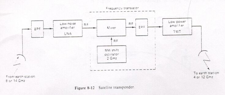
Transponder
A typical satellite transponder consists of :
1. An input bandlimiting device (BPF)
2. An input low-noise amplifier (LNA)
3. A frequency translator
4. A low-level power amplifier
5. An output bandpass filter.
Figure 6 shows a simplified block diagram of a satellite transponder. This transponder is an RF-to-R.F repeater. Other transponder configurations are IF and baseband repeaters similar to those used in microwave repeaters. In Figure 6 the input BPF limits the total noise applied to the input of the LNA. (A common device used as an LNA is a tunnel diode.) The output of the LNA is fed to a frequency translator (a shift oscillator and a BPF) which converts the high-band uplink frequency to the low-band downlink frequency. The low-leve/1 power amplifier, which is commonly a traveling-wave tube, amplifies the RF signal for transmission through the downlink to the earth station receivers. Each RF satellite channel requires a separate transponder.
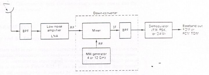
Downlink Model
An earth station receiver includes an input BPF. an LNA, and an RF-to-IF down-converter. Figure 7 shows a block diagram of a typical earth station receiver. Again, the BPF limits the input noise power to the LNA. The LNA is a highly sensitive, low-noise device such as a tunnel diode amplifier or a parametric amplifier The RF-to-IF down-converter is a mixer/bandpass filter combination which converts the received RF signal to an IF frequency.
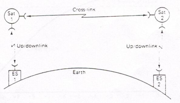
Cross-Links
Occasionally, there is an application where it is necessary to communicate between satellites. This is done using satellite cross-links or intersatellite links (ISLs). shown in Figure 8. A disadvantage of using an ISL is that both the transmitter and receiver are spacebound. Consequently, both the transmitter's output power and the receiver's input sensitivity are limited.
SATELLITE SYSTEM PARAMETERS
Transmit Power and Bit Energy
High-power amplifiers used in earth station transmitters and the traveling-wave tubes typically used in satellite transponders are nonlinear devices; their gain (output power versus input power) is dependent on input signal level. A typical input/output power characteristic curve is shown in Figure 8-15. It can be seen that as the input power is reduced by 5 dB. the output power is reduced by only 2 dB. There is an obvious power compression. To reduce the amount of intermodulation distortion caused by the nonlinear amplification of the HPA, the input power must be reduced (backed off) by several dB. This allows the HPA to operate in a more linear region. The amount the input level is backed off is equivalent to a loss and is appropriately called back-off loss (Lbo).
To operate as efficiently as possible, a power amplifier should be operated as close as possible to saturation. The saturated output power is designated P0 (sat) or simply Pt The output power of a typical satellite earth station transmitter is much higher than the output power from a terrestrial microwave power amplifier. Consequently, when dealing with satellite systems. Pt is generally expressed in dBW (decibels in respect to 1 W) rather than in dBm (decibels in respect to 1 mW).
Most modern satellite systems use either phase shift keying (PSK) or quadrature amplitude modulation (QAM) rather than conventional, frequency modulation (FM).
With PSK and QAM. the input baseband is generally a PCM-encoded, time-division-multiplexed signal which is digital in nature. Also, with PSK and QAM. several bits may be encoded in a single transmit signaling element (baud). Consequently, a parameter more meaningful than carrier power is energy per bit (Eb ). Mathematically. Eb is
Eb = Pt Tb (8-1a)
where
Eb = energy of a single bit (J/bit)
Pt = total earner power (W)
Tb = time of a single bit (s)
or because Tb = 1/ Fb , where Fb is the bit rate in bits per second.
![]()
Effective Isotropic Radiated Power
Effective isotropic radiated power (EIRP) is defined as an equivalent transmit power and is expressed mathematically as
![]()
where
EIRP = effective isotropic radiated power (W)
Pr = total power radiated from an antenna (W)
At = transmit antenna gain (W/W or a unitless ratio)
Expressed as a log.
EIRP (dBW) = Pr (dBW) + A, (dB)
In respect to the transmitter output
![]()
![]()
Thus
![]()
Pt = actual power output of the transmitter (dBW)
Lbo = back-off losses of HPA (dB)
Lbf = total branching and feeder loss (dB)
At = transmit antenna gain (dB)
Equivalent Noise Temperature
With terrestrial microwave systems, the noise introduced in a receiver or a component within a receiver was commonly specified by the parameter noise figure. In satellite communications systems, it is often necessary to differentiate or measure noise in increments as small as a tenth or a hundredth of a decibel. Noise figure, in its standard form, is inadequate for such precise calculations. Consequently, it is common to use environmental temperature (T) and equivalent noise temperature (T,) when evaluating the performance of a satellite system. In Chapter 7 total noise power was expressed mathematically as
N=KTB
Rearranging and solving for T gives us
![]()
where
N = total noise power (W)
K = Boltzmann's constant (J/K)
B = bandwidth (Hz)
T = temperature of the environment (K)
Noise figure equation
![]()
where
Te = equivalent noise temperature (K)
NF = noise figure (absolute value)
T = temperature of the environment (K)
Rearranging noise figure equation , we have
Te =T(NF-1)
Typically, equivalent noise temperatures of the receivers used in satellite transponders are about 1000 K. For earth station receivers T, values are between 20 and 1000 K. Equivalent noise temperature is generally more useful when expressed logarithmically with the unit of dBK, as follows:
Te (dBK) = 10 log Te
For an equivalent noise temperature of 100 K. Te (dBK) is
Te (dBK) = 10 log 100 or 20 dBK
Equivalent noise temperature is a hypothetical value that can be calculated but cannot be measured. Equivalent noise temperature is often used rather than noise figure because it is a more accurate method of expressing the noise contributed by a device or a receiver when evaluating its performance. Essentially, equivalent noise temperature (Te) is the noise present at the input to a device or amplifier plus the noise added internally by that device. This allows us to analyze the noise characteristic: of a device by simply evaluating an equivalent input noise temperature. As you will
see in subsequent discussions, Te is a very useful parameter when evaluating the performance of a satellite system.
Noise Density
Simply stated, noise density (N0) is the total noise power normalized to a 1-Hz bandwidth, or the noise power present in a 1-Hz bandwidth. Mathematically, noise density
is
![]() or
K Te
or
K Te
where
N0 = noise density (W/Hz) (N0 is generally expressed as simply watts;
the per hertz is implied in the definition of N0)
N = total noise power (W)
B= bandwidth (Hz)
K = Boltzmann's constant (J/K)
Te = equivalent noise temperature (K)
Expressed as a log.
N0 (dBW/Hz) = 10 logN- 10 log B
= 10 log k+ 10 log Te
Carrier-to-Noise Density Ratio
C/N0 is the average wideband carrier power to noise density ratio. The wideband carrier power is combined power of the carrier and its associated sidebands. The noise is the thermal noise present in a normalized 1-Hz bandwidth. The carrier-to-Noise density ration may also be written as function of noise temperature. Mathmatically, C/N0
![]()
Energy of Bit-to-Noise Density Ration
Eb/N0 is one of the most important and most often used parameters evaluating a digital radio system. The Eb/N0 ratio is a convenient way to compare digital systems that use different transmission rates, modulation schemes, or encoding techniques. Mathematically, Eb/N0 is

Eb/N0 is a convenient term used for digital system calculations and performance comparisons, but in the real world, it is more convenient to measure the wideband carrier power-to-noise density ratio and convert it to Eb/N0. Rearranging Equation 5 yields the following expression:
![]()
The Eb/N0 ratio is the product of the carrier-to-noise ratio (C/N) and the noise bandwidth-to-bit ratio (B/Fb) Expressed as a log:
![]()
The energy per bit (Eb) will remain constant as long as the total wideband earner power (C) and the transmission rate (bps) remain unchanged. Also, the noise density (No) will remain constant as long as the noise temperature remains constant. The following conclusion can be made: For a given carrier power, bit rate, and noise temperature, the Eb/N0 ratio will remain constant regardless of the encoding technique. modulation scheme, or bandwidth used.
Figure 8-16 graphically illustrates the relationship between an expected probability of error P(e) and the minimum C/N ratio required to achieve the P(e). The C/N specified is for the minimum double-sided Nyquist bandwidth. Figure 8-17 graphically illustrates the relationship between an expected P(e) and the minimum Eb/N0 ratio required to achieve that P(e).
A P(e) of 10-5 (1/105) indicates a probability that 1 bit will be in error for every 100,000 bits transmitted. P(e) is analogous to the bit error rate (BER).
Gain-to-Equivalent Noise Temperature Ratio
Essentially, gain-to-equivalent noise temperature ratio (G/Te ) is a figure of merit used to represent the quality of a satellite or an earth station receiver. The G/Te of a receiver is the ratio of the receive antenna gain to the equivalent noise temperature (Te) of the receiver. Because of the extremely small receive carrier powers typically experienced with satellite systems, very often an LNA is physically located at the feedpoint of the antenna. When this is the case. G/Te is a ratio of the gam of the receiving antenna plus the gain of the LNA to the equivalent noise temperature. Mathematically, gain-to-equivalent noise temperature ratio is
![]()
Expressed in logs, we have
![]()
G/T, is a very useful parameter for determining the Eb/N0 and C/N ratios at the satellite transponder and earth station receivers. G/Te is essentially the only parameter required at a satellite or an earth station receiver when completing a link budget.
SATELLITE SYSTEM LINK EQUATION
The error performance of a digital satellite system is quite predictable. Figure 9 shows a simplified block diagram of a digital satellite system and identifies the various gains and losses that may affect the system performance. When evaluating the performance of a digital satellite system, the uplink and downlink parameters are first considered separately, then the overall performance is determined by combining them in the appropriate manner. Keep in mind, a digital microwave or satellite radio simply means the original and demodulated baseband signals are digital in nature. The RF portion of the radio is analog; that is, FSK, PSK, QAM. or some other higher-level modulation riding on an analog microwave carrier
LINK EQUATIONS
The following link equations are used to separately analyze the uplink and the downlink sections of a single radio-frequency carrier satellite system. These equations consider only the ideal gains and losses and effects of thermal noise associated with the earth station transmitter, earth station receiver, and the satellite transponder.
Uplink equation
![]()
where Ld and Lu are the additional uplink and downlink atmospheric losses, respectively. The uplink and downlink signals must pass through the earth's atmosphere, where they are partially absorbed by the moisture, oxygen, and particulates in the air. Depending on the elevation angle, the distance the RF signal travels through the atmosphere varies from one earth station to another. Because Lu and Ld represent losses, they are decimal values less than 1. G/Te is the receiving antenna gain divided by the equivalent input noise temperature.
Expressed as a log.
![]()
Downlink equation
![]()
![]()
Expressed as a log
![]()
Figure 8-18 Overall satellite system showing the gains and losses incurred in both the uplink and downlink sections. HPA. High-power amplifier Pt HPA output power: Lbo back-off loss Lf feeder loss; Lb branching loss; At transmit antenna gain: Pr total radiated power = P, — li*, — Lt, — L,. EIRP, effective isotropic radiated power = P,A,: L,,. additional uplink losses due to atmosphere: Lp path loss: Ar, receive antenna gain: G/Te gain-to-equivalent noise ratio: La, additional downlink losses due to atmosphere: LNA. low-noise amplifier; C. T,, carrier-to-equivalent noise ratio: C/N0, carrier-to-noise density ratio; £t>/'.V3. energy of bit-
to-noise density ratio C/N carrier-to-noise
for more information regarding this subject
please send mail to [email protected]
This page designed as homework for material EE526 as part of the master degree in Electronics & Communication Engineering in King AbdulAziz University