If you've a photo of your preamp, I'd certainly be interested to see it.
Send me a picture/description.
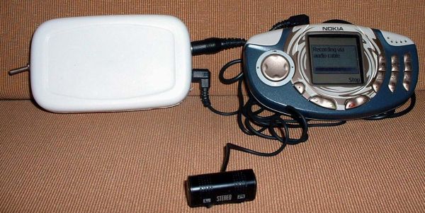
I have a Nokia 3300 mobile phone which can also make audio
recordings. I wanted to use my phone for making live recordings of concerts.
But since the phone has only a "line-in" socket and no "mic"
socket, so I
was looking for a circuit for making a microphone preamp for boosting the
microphone output to line level. I wanted a preamp with a good performance
which would also be easy to construct. Your circuit is just what I needed.
Thank you very much.
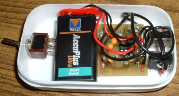
I have made one preamp exactly as per your circuit except that I have
omitted the 2pF high frequency rolloff capacitors. It is working fine, but I
have not yet put it in an enclosure. I have also made a second, "no frills"
version of your preamp which does not have the gain control switch or the
output level control pot. The gain is fixed at the maximum level of about
23. I am attaching some pictures of my preamp.
For me, the hardest part of this project would have been making the PCB. I
bypassed this step completely by ordering the PCBs from a professional PCB
maker. Since, he was not willing to accept an order for just one small PCB,
so I had to order more PCBs than I needed. I have a few spare PCBs. If any
of your readers is interested, he/she may contact me at![]()
(Email address is a .gif to block spam, so type it manually.)
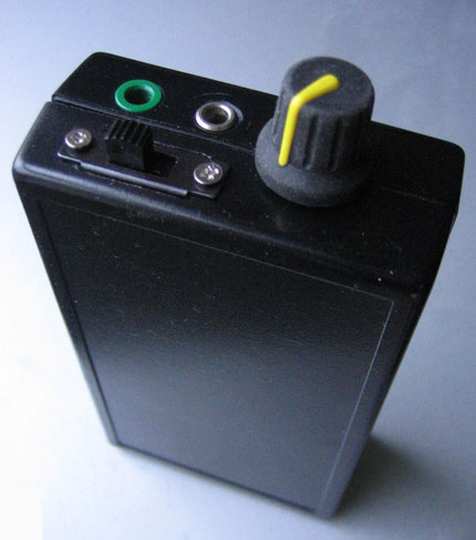
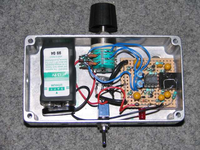
Great circuit! I built this yesterday and it works great - many thanks.
I have attached a photo if you're interested - nothing is labelled yet,
but the green jack is mic in, other jack line out (with internal switch
for power supply). Pot is for gain, as is the switch. I used your
design exactly, but might modify it slightly if necessary. I thought it
might be nice to have a rotary switch with say 10 different gain
settings instead of the pot.. might prevent accidental movement of the
pot.
cheers
James
Je me permets de vous contacter simplement pour vous communiquer une adresse
web
où j'ai mis à disposition des internautes, des tests audios relatifs
à de l'enregistrement LIVE en encodage MP3 direct
sur l'entrée LINE-IN d'un SAMSUNG YP-T7FX après avoir réalisé
le montage "préamplificateur stéréo"
expliqué et détaillé sur votre site web.
Si vous jugez utile de mettre ce lien sur votre site web...
http://stephane.aubert.free.fr/SAMSUNG.YP-T7FX/
(Sorry I don't know what Stéphane said but check out the pictures on his website.)
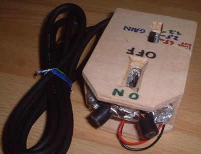
I've built your simple stereo ECM preamplifier, integrated in my DIY microphone,
and it works amazingly well ! I use it mainly for acoustic testing stuff, and
also occasionaly for stereo music recording.
I built it double supply rail, with a 3 positions switch for gain. I changed
the feedback resistors to have more gain with my ECM capsules which are not
big, but have a very good S/N ratio.
I have a website so you can have a look at it :
http://www.freazer.com/perso/youyoung/micro.html
You can add this link to your page, so it would add another design to your website.
I built the thing out of NE5532s in the end... Took an age to do, as
all the other components were SMT to fit it onto a really tiny board
which'll fit inside one of those Otter Boxes along with the MD unit...
I don't think the numerous SMD components are even visible on the
underside shot due to the focus being so poor, but I've included it anyway.
As for layout, well, I tend to make it up as I go along... effectively, the
underside could be quoted as 3-layer... :)
As for the components used... all the resistors are SMD 1% bulk metal films.
Power decoupling is 220uF/25V FC+10uF/25V Oscon. Coupling caps are all
2.2uF/25V Oscon except for the blocking ones on output which are Elna
Starget 10uF/35V.
- Tom.
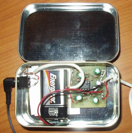
Thanks for the preamp circuit. I scaled your circuit design (407 dpi)
and printed it onto toner transfer medium, ironed it onto a copper-clad
and built one today. Here's a photo for your collection.
It works nicely tucked into an Altoids tin. Nice sheilding I guess. I
used a TL072 and shorting jumpers for the gain control. No fancy
components, just carbon resistors and electrolytic caps. I didn't have
2pf caps for the feedback bypass so I used 5 pf and that seems to work fine.
The pre-amp is working well. I've used it with a mini-disc and an
Archos Jukebox recorder and a pair of home-made binaural mics to do
environmental recordings. Got some great thunder a while back...
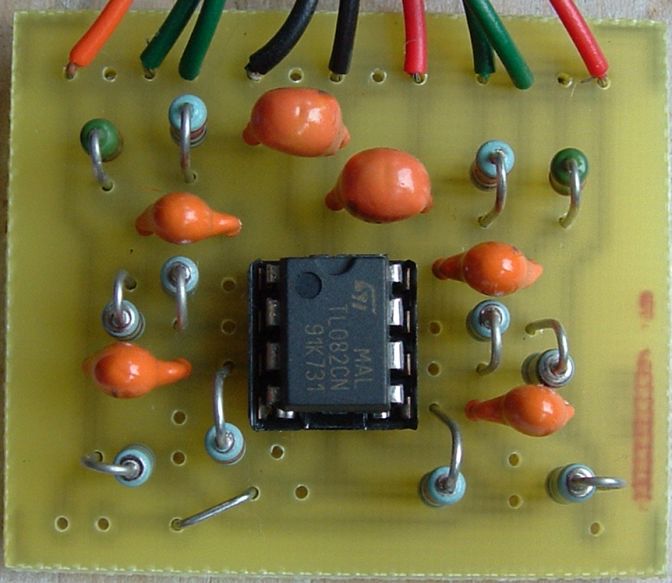
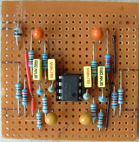
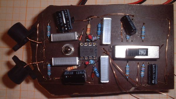
Saving the worst for last. OK these will hopefully give some idea about stuffing
the thing. Note that this is an early board, and there is a mistake. The top
left and top right resistors should be swapped in position with the capacitors
that feed them. The PCB artwork on the other page is correct.
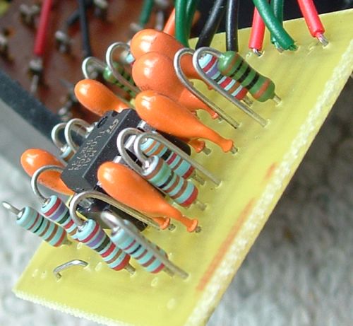
If you're really tricky you'll be able to read the resistor codes here.
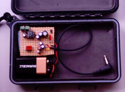
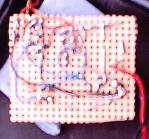
Below is my prototype, built on veroboard. If the
spare tracks around the outside were trimmed it actually
wouldn't be much bigger than the PCB version. You may be
able to spot that there are two input capacitors on the
veroboard version. That's because I was playing about
with a switchable input filter, for a selectable bass
cutoff, as seemed to be popular on some battery boxes.
But it seemed to have essentially no effect to me,
I guess being a one pole filter and all, so I left it
to its own devices.