...find attached
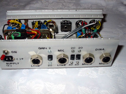
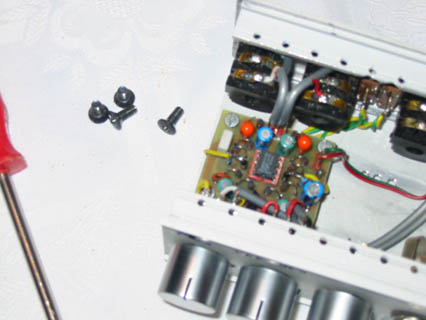
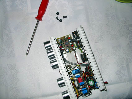
some pictures with the preamp finished inside its
clousure. Also I've appended the schematic. Plus the printed circuit board
(double size).
I appreciate your help and I would like to thank you by sending you these
pictures. If you consider to include them in your web page I'll be happy.
One comment on
components: I've used a 5532, so the circuit has two preamps.
The schematic represents one half, all components are named as: R1, R2...
C1, C2... For the second half components on the printed circuit board are
named as follows: R21, R22... C21, C22... that is I've pre-appended a "2"
referring the second half.
I've meassured Gain and Frecuency response and it is quite fair, nearly flat
from 20Hz to 20KHz.
Two ranges 20dB (Gain x10) and 40dB (Gain x100)
Hope this is useful and it's clear. You can address any question to me and
include my e-mail.
Best regards, Juan <[email protected]>