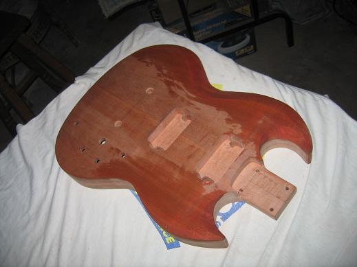
2 July 2006.
Lots of practice, but some results too.
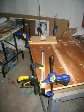
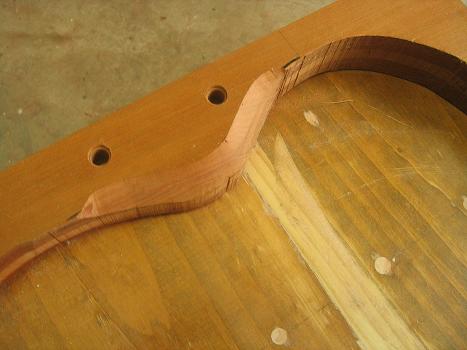
Photo 1. In search of the perfect template...
I felt I could get a better fit by making a template for each neck using the Martin Koch method. Line up two straight boards and use them to guide the router.
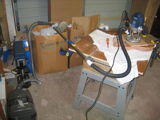
Photo 2. Basic set up.
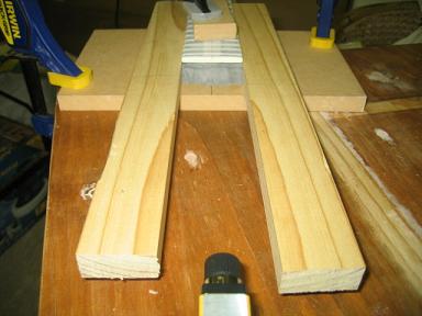
The grey stuff is epoxy which I forced against the end of the neck to produce a negative shape of the end curve. My theory was that it would stick to the board from which the template would be cut and act as a guide for the router. Even though I lined the end of the neck with grease proof paper, the epoxy came away stuck to the papered neck, not the template board...Oh well...
Since this whole blog is mainly for amateurs, I'm putting in the blind alleys and back ground stuff since this is what eats up the time, but produces the necessary time on the tools, and understanding of what's feasible.
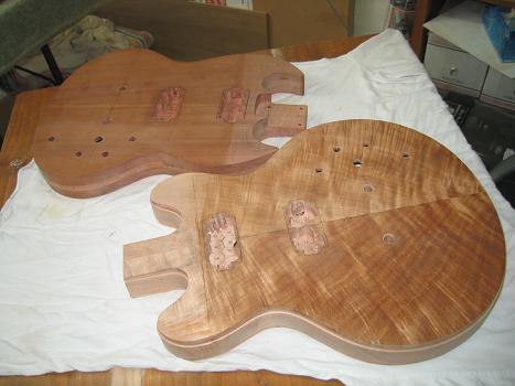
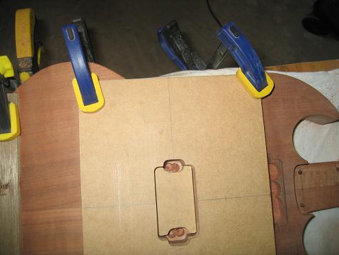
Photo 3. Rough Cut.
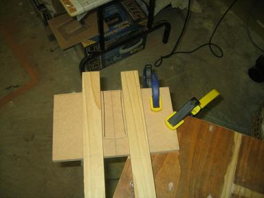
I routed down using the boards as guides, then taped the StewMac template across the bottom with the curve on the line. This gave a better fitting shape.
Now...how am I going to carve the top of the SG? I don't have many measurements so I will be extrapolating the shape from lots of pictures. I had thought a 45deg chamfered router bit might work. It has a ball bearing to follow the body shape, and increasing the router depth step by step gives a cut stepped along the length which can be cleaned up with sureforms scrapers and good old sandpaper.
Photo 4. Practice for SG top carve
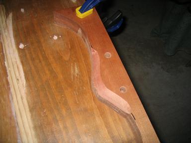
This came up very well..
Photo 5. Another look
I felt confident that I could produce a reasonable job. The main difficulty was that the deeper routes had a vertical edge at the top once the depth of cut exceeded the height of the chamfer...order a bigger bit!! LOL!
As luck would have it a friend dropped in for lunch. Rob is a sort of all round building guy who accepts small government jobs to repair and maintain Housing Commission dwellings...can you imagine what he is faced with? We won't go there!!!
Anyway I showed him the above practice cuts expecting at least some mild enthusiasm...but he looked bemused & asked "Why are you using a router? Why don't you use one of these?" & produced a Power File. I never dreamed they existed. They're like a mini belt sander...I had a bit of a play with it...yes this was the way to go! Down to the hardware shop to place an order!!
Photo 6. Mark out the cut..Take a deep breath...
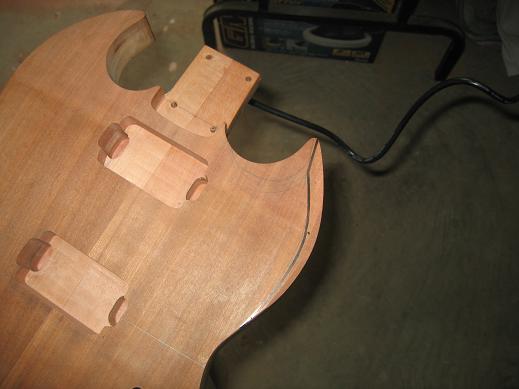
and ...cut...this is a for real...
Photo 7 . Lower side of top DONE!!
It works...As I said I spent a lot of time trawling books & the net for photos at various angles so I could infer the shape of the carves. They are not constant 45deg bevels but change along the length of the cut. Well..mine do!! LOL.
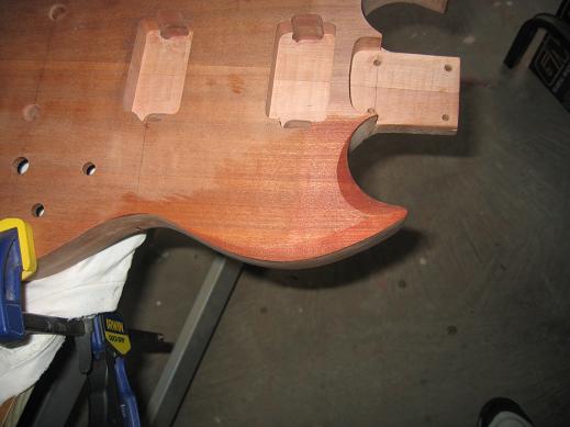
You can see a slight wobble in the outline on the top. It's due to the 3deg angled back carve of the top that was done to give the right neck angle in the neck pocket. The things you don't think of. I will true it out later.
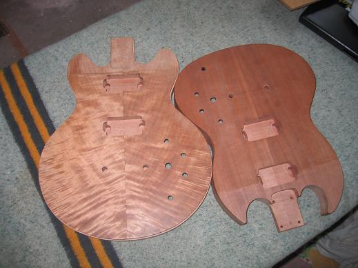
Photo 8. Top complete.
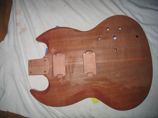
Photo 9. from another angle.
I wet the top to try & show the results more clearly. I am satisfied with the job, but some cleaning up with sanding & scraper needs to be done.
I can't get any photos of the back, so while I know the back is carved, I'm simply going to round the edges over to a 1/8" radius. I can't go round ripping of Gibson now can I?
Did you notice the pickup cavities? This is their story.
Photo 10. Drill out as much as you can.
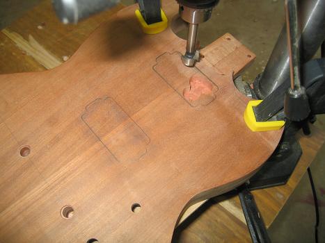
Photo 11. All cavities drilled out.
The curvy shape of the 336 made it impossible to drill out the bridge pickup cavity completely. There is quite a bit of waste wood still there. Out with the chisel!
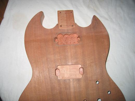
If you look at the neck pickup cavity on the 336, you'll see a black mark. That is the entry of the wiring channel routed way back before the top went on. The black colour is conductive paint. Now..wait..where is the wiring channel for the bridge pickup? It better be there LOL!
Photo 12. Another view.
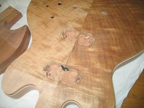
Photo 13. Now lets get the router...
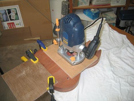
Photo 14. You'll need a dust extraction system!!
You gotta love duct tape!! LOL!
Photo 15. For the deep side cuts I used a little insert
This isn't really necessary, but I thought I'd go for the full production. It didn't stick well because lots of router dust was blown under it. I only used the top one since the bottom shape is not a good match to either template end.
Photo 16. One down, three to go
.
Wow....it's just like a bought one!!
Photo 17. All done!

...and there's the wiring channel for the bridge pickup. That's a relief!.
Photo 18. Another pic.
I just love that figured top. I certainly lucked in on that piece!!
The next immediate task is to route in the carve on the CS336. A series of carves is done from the inside out each one slightly deeper than the one before. This gives a profile of steps that can be smoothed out with rasps , planes, SANDPAPER to give the shaped curve. I have to take care to get the ultimate depth just right so then the binding will sit just proud of the top. It can then be scraped back after the top is stained. Lacquer will go over the lot.
I have practised a bit free hand and Have some confidence. However the 3 deg angle in the top threw me a curly one just as it did in the SG carve.
The best way out of this is to use the top carve jig designed by Anthony Setchell a British luthier. Google 'Anthony Setchell' it will be worth it.
Photo 19. The bits for the jig.
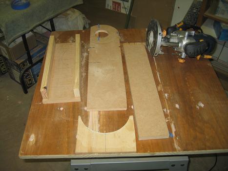
The semi circular piece on the bottom was made to be part of a binding channel jig, (but my router didn't have the necessary holes through the router base) and I thought I might use it to 'fix' the position of the router, but instead I drilled holes coincident with the recessed holes in the base and cut some 1/8" galvanised nails to the necessary lengths so the router will sit down on them and fix it's position. The position will always be the same. You can see the 'studs' wrapped in blue tape to firm the fit in the holes in the router base.
Photo 20. The Setchell top carve jig.
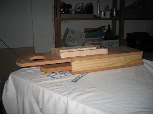
I screwed and glued the narrow 'ribs' on top as an extra because the top flexed a bit under the weight of the router. I wanted to minimise if not eliminate the flex.
Photo 21.. with the router on
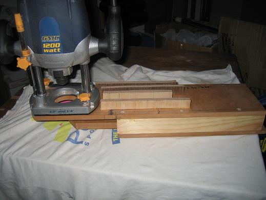
The guide or tongue moves back into the 'box' to give the width of choice for a cut. The router height determines the depth. The adjustable tongue is held by a clamp that is holding the jig to the bench. There's no need to 'set' adjustments since they're all relative to the zero position of the router bit. This will change with changes in bit size.
The guitar body is fed through under the router and pushes up against the guide (or as I keep calling it) or tongue.
I had hoped to produce some practice curves, but as luck would have it my router switch is defective in that it won't 'Lock ON' . That function is necessary for the operation since I need both hands to feed the body through. Well it's under warranty & I should have a replacement by Thursday.
I'll sand down the SG to as near finished install the earth wire & Tailpiece studs, string up mark the bridge post positions, drill the holes press in the posts then (maybe) stain & lacquer up. LOL Nothing to it!!
Thanks for viewing. RobSm.
Page List - Much less editing doing it this way. LOL!!