8 – 16 January 2006.
The construction of the CS336 requires gluing on a separate top and a back to a rigid frame.
The lugs for the control panel screws have been formed when the ‘chambers’ were cut and cleaned up.
The choice at this point is to either:
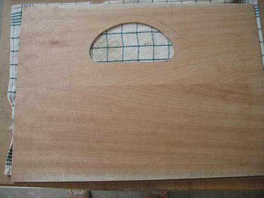
1. Glue on the back after defining the position of the control panel cover and then cutting it out
2. Cut out control panel cover first and then glue.
I chose to cut out the control panel cover hole first because I could see where things were going and if done after gluing I would have to be ultra careful about not cutting or routing into the frame.
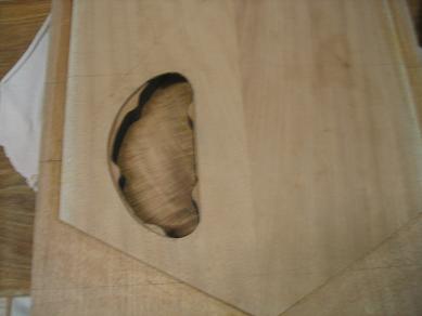
Picture1. Control Access cut into back.
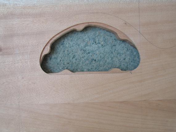
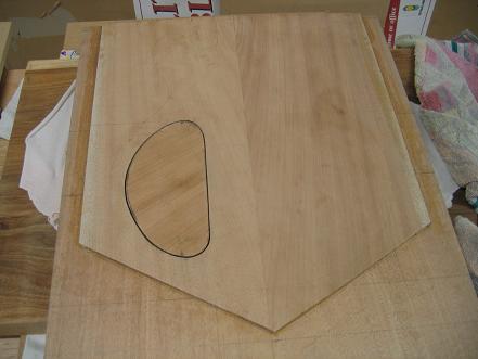
Picture2. It fits OK.
In a number of books, the shape of the instrument is drawn on the top & on the bottom pieces, cut to a ‘rough’ shape and then top & bottom glued on.
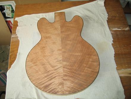
I chose to draw datum lines on the chambered blank so that I could glue on top & bottom line up the original template with the datum lines and have the shape cut once with a band saw. I have seen this approach used by Dave Ormandy on his Ridgeway Guitars web page.
http://www.ridgewayguitars.pwp.blueyonder.co.uk/homepage.htm
I read up in the books on gluing and it is given about a line and a half.
Now is the time pass on a little hard info to beginners about a couple of near misses that have been due to my inexperience but which have not cost me dearly.
Interior Routing.
I routed the wiring channels before I cut & cleaned up the chambers because it was a smaller easier job. When cleaning up the chambers with the router, the bit followed into the mouths of the wiring channels. This effect is mentioned in the books but in the context of the jack plate hole in the side of the body..ie rout the sides clean first then drill the jack hole to avoid this.
The result is a couple of ‘dips’ in the surface on which the control panel cover will rest. Luckily this will have no consequences that I can imagine except that I know it happened!!
Take care if routing across ‘open’ channels. Avoid if possible. In my case I could have avoided it at one end, but the routing into the pickup cavities has to be done before the top goes on and it might not be possible to ‘cover’ the entrance. I could have used the drill from the neck pocket option. That would have avoided the problem, but as I said my inexperience did not allow me to foresee it. And I am some way from doing the neck pocket since my Rockler tools order has not arrived.
Well as luck would have it my Warmoth order arrived containing the necks and the LPS lam to body. The family were impressed!!
After checking things I looked at the way Warmoth do the interior routing to avoid the above little glitches.
The wiring channel for the bridge pickup has been drilled after the top has been glued on. It’s short so there you go. It should be no problem to do that.
The longer channel to the neck pickup is routed before the glue up, but the channel stops just short of the pickup cavity and then they drill a short (1/4” dia) hole from the pickup cavity into the routed channel.
So for glue on top projects I can offer up these minor but real life tips on things so far:
1. Rout the control cavity before the neck pickup wiring channel
2. Stop the wiring channel rout for the neck pickup just short of the position of the pickup cavity
3. After the top is glued on and the pickup cavities routed cleanly drill the remaining section of the neck pickup wiring channel and drill the wiring channel for the bridge pickup.
Glue up.
I cut the bottom excess off the back laminate so I could use it to make the control panel cover and maybe to do more dye testing. No problem in theory.
I did a ‘dry’ run in gluing on the back, making sure that I could fit sufficient clamps and cauls to hold the laminate down. No problem lining up the datum lines on black and back laminate.
The instructions on the tite bond said apply thickly…. so I did. I also applied glue to both surfaces though nothing explicit was anywhere on the bottle.
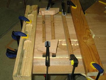
Lining up the datum lines was easy but holding the
laminate in position as I tightened the clamps proved impossible. I was mindful
of the glue going off and it seemed that every time I made one adjustment to a
clamp, the laminate moved! Frustrating.
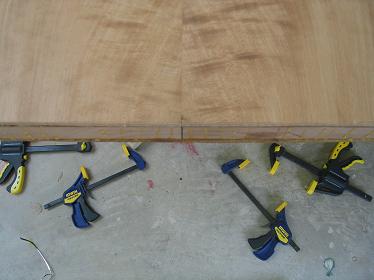
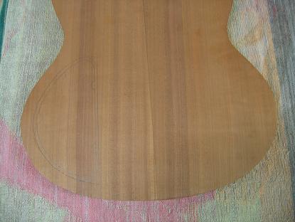
Picture 3. Gluing on the back laminate.
Eventually I felt I had it and locked it down.
In cleaning up the exudate of glue after 45mins or so it was clear that the centre lines were out at one end by something between a bee’s dick and a smidgen (that’s slightly more than a gnatsdick) . Not a real problem I thought because it is so close that no one will ever see it. However the laminate also moved UP by quite a bit more and given that I’d trimmed off some timber BEFORE gluing as explained above I realised that if I lined up the top properly and cut to the template I might not have any back laminate on part of the cut out shape. I checked and am happy to say that if the top is correctly aligned and the template correctly aligned, then the body will be all OK except that the centre line of the back laminate will be very slightly off at the bottom. I believe no one would ever notice..but the project might have suffered a major setback.
Picture 4. Hmmmm…thinking…
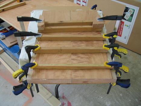
How to glue to top on…I will NAIL it in position before tightening the clamps!!.
Picture 5. Positioning all set.
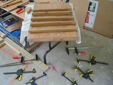
The top glue up seems to have gone well with a simpler configuration of cauls and less tension about the glue going off too quickly. The cauls are convex with leather glued to the convex surface. When clamped down at the ends the curve initially touching only in the centre is flattened and pushes the glue from the centre to the edges. They were kindly lent to me by Chris the friendly band saw guy.
Picture 6 and 7. NAILED before Clamping.
Picture 8. Top Glued & Clamped
I am concerned about the width of the glue line but I won’t see it until I get the body back after it’s cut to shape on the band saw. While he’s not exactly a mentor at this stage Chris has always said to ring him anytime. So far I haven’t but I wish now I’d talked to him about gluing before doing it!! LOL…
I also made the control panel cover without incident except that I was getting pissed off because it was taking so long to arrive at the final shape…and then I noticed how shiny the surface was…the sandpaper on my dremel was ‘used’ and all it was doing was polishing the timber…LOL..yeah there’s one born every minute!!. After changing the sandpaper the cover was shaped quickly and I’m happy with it. I did make it significantly smaller to allow for finish on both surfaces so I will have to wait to see ultimately how tidy the fit will be.
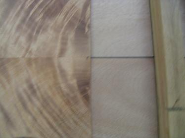
Picture 9. Control cavity after glue. Darkness is from conductive paint.
There were a couple of slips with dremel on the cover but they should sand off OK.
Picture 10. Cavity cover fits OK.
There’s a lot of pencil on the wood that makes the photo look odd. It will sand off OK.
I also laid out the control panel drawing on the SG. You gotta watch things when you’re working on one surface with templates & plans & then flip the blank over & work from the bottom. There were no dramas…just check check check.
Picture 11. SG Contol cavity & cover drawn on back of blank.
After the body comes back from the band saw serious stuff starts. From all I read I should get the neck pocket right, locate the bridge and do a string up & nail the intonation and bridge position. On the other hand I have plans and it is tempting to trust in the plans and drill where they indicate.
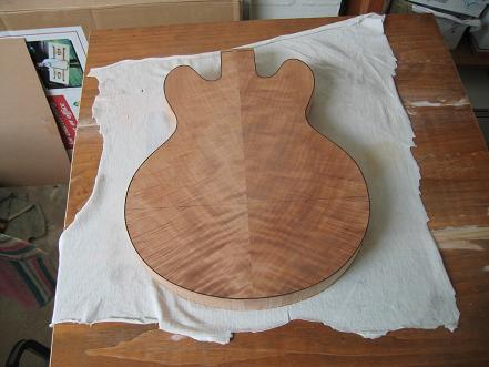
I picked up the body from Chris who owns the resaw bandsaw today. Here are three pictures of the shaped 336 body. It inspires me!! LOL.
Picture 12. 336 body rough shape 1.
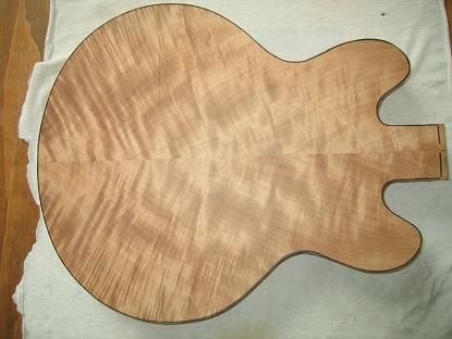
Picture 13. 336 body rough shape 2.
Picture 14. 336 body rough shape 3.
The next week will be spent practising with various tools need in the successive stages ie. Drill stand with various bits and sander drums and the routerre mounted on it’s router table. I’m not sure whether this will rate a picture show or not. I something wild happens I’ll post it.
Remember this…”if at first you don’t succeed, try not to act surprised…”
CYA.