Conventional controller and predictive controller
In this case, the physical system is the rocket, the input is the actual rocket inclination, the reference signal is the desired rocket inclination. Those signals are subtracted to obtain the error signal, injected on a controller and the output from the controller is the thrust direction.
By directing the thrust, as soon as the rocket starts to fall in one direction, the controller will make it return to the desired inclination. But if the correction is too strong either because the controller is too slow on calculating the correction or because it was not well designed, the rocket will actually start to fall to the opposite side after the correction.
A certain amount of oscillation will always happen, but if it tends to increase in intensity, the rocket would start to oscillate more and more until the moment the thrust cannot be direct laterally as much as needed and the rocket would finally fall laterally.
Another example of a controller is the automatic pilot of an airplane. Considering the altitude control a case apart, based on the airplane position P(composed of two coordinates, latitude N-S and longitude E-W) and the reference ( latitude and longitude), the automatic pilot will dictate the amount of aileron (what will make the airplane to roll) and the rudder in a coordinated way to direct the airplane to the desired route.
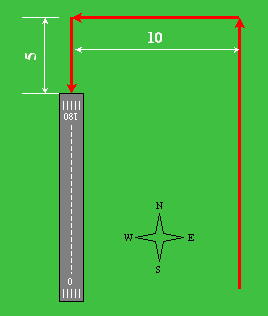
Suppose the approach charts just dictate the following: Come heading North parallel to the lane at 10 miles east, pass the lane 5 miles and take West, fly 10 miles and take South, fly more 10 miles and l
A pilot would be able to follow this chart very closely, because as he knows the airplane responds slowly, he would actually start to make the curve before the points determined by it, so the airplane won't deviate too much from the route.
But a controller works based on the error signal. That means it will only start to react when the points passes. So the result would be very poor because on every change of direction, only after passing straight the point, the airplane would start to react, turning to go back to the route.
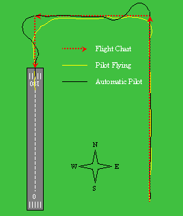
In reality this isn't such a critical problem for aircrafts, but it illustrates well the application of a predictive control.
For a robot arm, that has to follow pre-programmed movements, the precision of the movements suffer every time there starts an acceleration or de-acceleration on one joint. In every system that it is applied, a predictive control allows for a response with less error and a less strong command signal because it in certain way doubles the time of reaction. That means, a conventional controller would react only after some change in the reference, while a predictive controller would react both before and after such an event.
Of course, one condition is necessary: The reference signal must be known in forehand, because the predictive cannot guess the future.
For external perturbations (all those random perturbations that are not predicted), the predictive control will react as a conventional controller, but in a somehow optimized way.
The mathematical deduction of the method is what you find on the books, i.e. a set of generic mathematical equations that represent a generic system and with symbolic manipulation result in the formula that will be used to find the gain vectors.
The complete mathematic description of the GPC method can be found on literature mentioned below. This part is only to give a general understanding of the concepts related to the GPC method.
Once a method is determined, it can be applied for a particular system (the system you want to control), which has a determined behaviour in terms of inertia etc. that is represented as Hp(p).
The calculation of the gain vectors is the synthesis of the controller and in our case a program in Matlab was used to automate this part because the calculations are somehow complicated.
And a major advantage is that they can be performed in an automatic way because its synthesis does not rely on empirical or subjective evaluation of the results obtained.
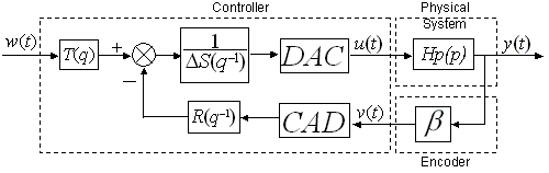
The synthesis of the controller depends only of Hp(p) and a few parameters and as input: The prediction horizon (in time intervals), the delay between the input of the input and the output on the controller (usually 1 interval) and a moderation factor that limits the response of the controller to assure stability.
The calculation of the controller output is our third separate instance. This is actually the real-time algorythm that is implemented on your controller.
Those are very simple vector operations using the previously determined gain vectors (here they are considered as constants), the input from your physical system from a ADC, a vector with the reference at the current time and for the next intervals and a vector with historical output values.
That calculations will result on the output value, that is put into your DAC to actually control the system.
Only in case Hp(p) may vary a lot, you may need to re-calculate the gain vectors for your controller "on the flight". This would be the case of a robotic arm, for example, in which the rotation inertia will vary dependin if the arm is extended or retracted.
And this calculation needs to be done every time your system characteristics have changed enough to reduce the performance of the controller. So it does not need to be calculated at the same rate the controller operates.
A conventional controller uses only two gain vectors, one for the error signal and other for the output. The GPC uses instead tree separated vectors of gains, one for the reference signal, other for the output of the physical system (the feedback signal) and another at the output of the controller.
The reference signal is injected to the controller with an advance of some intervals (equal to the prediction horizon) what may be mathematically represented as a fictitious q^n block or by the gain vector on the reference signal being a pholinomial of q instead of q^-1.
The calculation of the output signal is performed as conventional discrete-convolutions between each of the signals and the corresponding gain vector, what can be easily implemented on a computer or microcontroller.
The deduction of the method passes through the description of the response for a generic system being described mathematically, composed of a free response part and a forced response. This response then is transposed to the future on a generic instant t+j.
Effectivelly the synthesis of the GPC will be the creation of a minimization criteria, where the error, present and future (within the prediction interval) will be mathematically represented and minimized by using Diophantine Equations. That will give a series of command signals that, if applied to the system will minimize the error. From that series of signals only the first one will be used, because perturbations exist, so it will be necessary to recalculate the output for the next time interval and so on. This is called the principle of the floating horizon.
The effective calculation of the command signals can be represented under the RST format, being RST constant-value vectors. That means once those vectors are mathematically determined (in other words, the controller is mathematically sinthetized), just easy calculations will be performed "on the flight", resulting in an easy to implement algorithm.
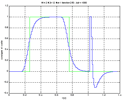
The system predicts the near changing of the reference signal and moves the physical system in advance, in a way to minimize the total error. That means the system has twice the time to respond to the reference signal, before and after the change on the reference..
At t=1s, there is an external perturbation to the system. There is no predicted response for that, as the controller does not have a crystal ball to predict the future. In this case the GPC is also effective, bringing the system back to the reference in a fast and stable way.

BOUCHER, P., DUMUR, D., La commande Pr�dictive, �ditions Technip: France, 1996.
Summary of the GPC theory (in French), at Sup�lec University