It All Goes Back Together
Like This:
This portion describes how we assembled the short block.
Wednesday 6/5/02
Received a package form SpitBits.. Inside were all the things that I ordered: Rod bearing set .030 over, main bearing set .010 over, core plug set, woodruff key, thrust washers: standard and .005 over, shims for crank, camshaft lock plate, 3 pc Borg & Beck clutch kit, clutch alignment tool, pilot bushing, air filter, air filter gasket, exhaust stud set and bonnet cones.
I tried to remove the old freeze plugs from the block. Do not believe the manuals. The Hanes, Bentley and the” Do it Yourself Guide to Restoration” manuals had these things just popping out on their own. One used a screwdriver hammered into the center and then prying out the plug.
I tried to pierce the plug with a screwdriver, no luck. I then used a small cold chisel to pierce the plug, success, but at a price. This method pushed the plug farther into the block. I then tried to wedge the plug out with the screwdriver and broke the end of the screwdriver. Luckily I was able to find both pieces of the screwdriver on the garage floor.
The other manual had the pictures of piercing the freeze plug with a center punch, and prying (prising in British term) it out. Tried this, bent the center punch. The punch pierced the plug nicely, but could not get the plug out. Went downstairs into the work area and found, under the workbench the slide hammer.
I purchased the slide hammer when I was 17 years old to do some bodywork on an old car. After punching several holes using the slide hammer I succeeded in making swiss cheese out of the fender. I wound up replacing the fender, and putting this thing away. Out it came.
I punched a hole with the punch and screwed the slide hammer into the hole and started to pull the plug. All this did was to put a dome dent in the plug. The next thing I tried was to put a hole in the edge of the plug and use the slide hammer. SUCCESS!!! This worked so nicely, that I tried it again, and again, and again. The next thing I new all the plugs were out.
Pictures:
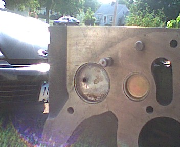
Plug with hole punched and ready to be pulled
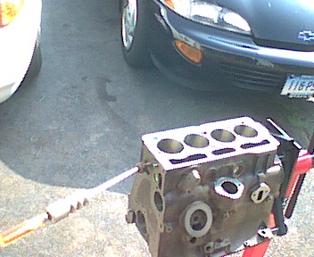
Puller attached and ready to pull
Start pulling the side ones. Note I've punched both holes first
The next thing on the menu to today was to size the rings and install them on the pistons. After going to the parts store to buy a set of feeler gauges (with four kids and a wife things are always missing) I was ready to start. I inserted the first ring into the number one cylinder and checked the gap with the new feeler gauge. The gap was .004 and the manuals give a range of .012 to .022. I removed the ring and used a small file to remove some material from each end of the gap. I installed the ring, checked the gap, now .011. Removed the ring and filed a little more to get a reading of .015. I did this with the second compression ring and stopped when I got a gap of .016. I then installed the oil rings on the number one piston, then installed number 2 compression ring, followed by number one compression ring. These steps were followed for number 2, 3, and 4 pistons.
Saturday 6/8/02
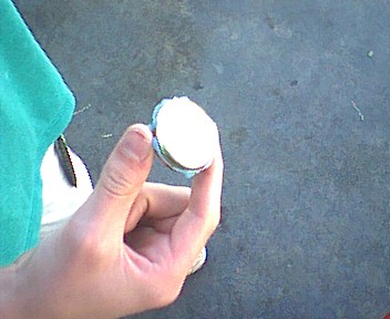
So much work to do, so little time to do it. Today was spent installing all the freeze plugs that I removed on Wednesday. I put in the first one while showing my son how to do it. I’ve never done one before, so it was a learning experience for the both of us. The first this we did was to get all the tools and supplies together. Picture here
We applied a coating of permatex blue sealant, then tapped the plug in with a hammer and socket that fit inside the plug. This was an easy job, we took turns putting the plugs in. The only one that gave us a problem was the one fitted in the back of the block next to the engine stand.
Pictures:
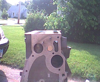
All gooed up and ready to install
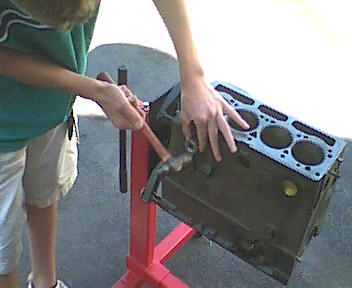
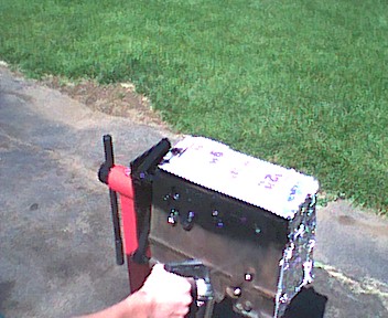
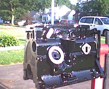
After all of the plugs were in we cleaned the outside of the block with break cleaner in preparation of painting. Tape was applied to all surfaces to be free from paint along with newspaper. My son was responsible for covering the front of the engine. He decided to use aluminum foil as it was easier to mold into place than paper. Pieces of paper towel were placed in holes to block any paint for coating the threaded areas.
The block looks shiny and new after 5 coats of paint. Eddie did most of the painting, while I did some of the touch up areas on the first coat. He did all of the painting after that. Next thing on the list was to get the area ready for assembly. The block sat in the driveway sun drying while we spent he time dusting the contents of the garage. When that was completed we swept, vacuumed, vacuumed again, and wet mopped the floor. All of the tools were cleaned and prepared for the big day.
More Pictures:
Sunday 6/9/02
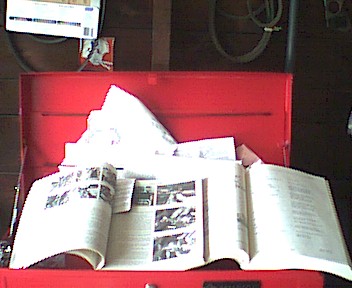
The big day has arrived. It’s time to start putting this baby back together. Things started off great. We were neat and organized. Let the pictures show you.
Pictures:
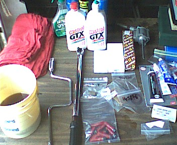
The worktable in this picture you’ll see the edge of the folding table that I have been using as a workbench. As my garage is only one car and I have to store the car while I’m rebuilding the engine, this folding table works out great. Just fold the legs and lean against the wall when done, or when moving the car.
On the back of the table are 2 quarts of Castral 20/50 motor oil. One of the quarts was poured into the bucket on the left for dipping the pistons before assembly. The other quart bottle is fitted with the top of a dish detergent bottle pop-top. These tops are great for topping off your lawn mower, oiling chainsaw chains, filling dashpots, and when you have to oil parts going into an engine rebuild.
Other things that are found in the picture are the torque wrench, speed wrench, Cosworth connecting rod bolts (in the plastic bag with red protecting covers), other miscellaneous bagged parts, engine assembly lube (in the black tube) permatex gasket sealers, and a oil pump rebuild kit. I chose the rebuild kit as the original pump housing was in great shape with no signs of wear and I just couldn’t just throw it away.
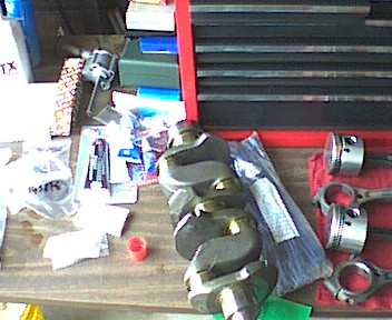
Another shot of the middle of the table shows the crankshaft as received from the machine shop, pipe cleaners to be used cleaning the oil passages, and a partial view of the pistons. In the back of the picture against the edge of the toolbox are the precision instruments that I’ll use. There is a 0-1” dial indicator, magnetic stand, 0-1” Starret digital micrometer, 0-12” calibers, .015-0-.015 dial indicator, and a 6 inch height gauge. You don’t need all of these but I have them, as I was a machinist in a previous life.
The pistons and new ring compressor and all of the reference material completes the shots of the workbench.
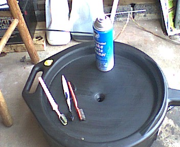
The cleaning area to wash parts with kerosene, and this area for greasy parts that need brake cleaner.
Let’s get to work:
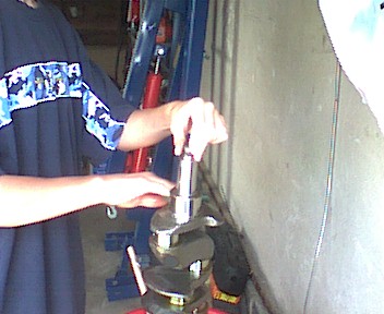
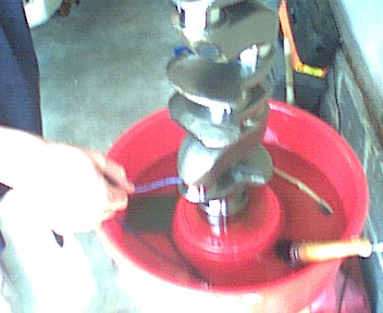
First thing we did was to clean everything. Her are some pictures of my son cleaning the crank shaft. In this picture he is holding the crank in the kerosene ready to clean. Notice he’s not wearing safety glasses? That was immediately changed. Although this picture did not come out as clear, he’s wearing glasses now. He kept them on for the rest of the day. It’s just not worth the problems that could happen by not wearing safety glasses. He is scrubbing the journals with kerosene and a green Scotch-brite pad in this picture. Pipe cleaners were used to clean all oil passages.
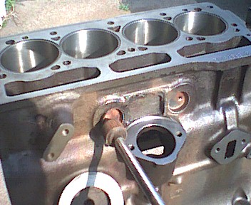
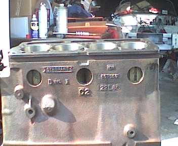
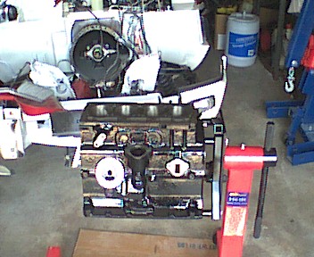
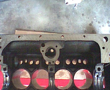
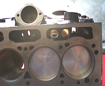
I was working on cleaning the block in preparation of assembly. This picture shows the block before cleaning. Note that I placed a large piece of cardboard under the engine stand. This was to cushion anything that I might drop (as in thrust washers) while we were assembling and to give some protection to the cement floor from the kerosene and oil that was used in cleaning and assembling the engine. Shown here is a picture of the bores after cleaning.
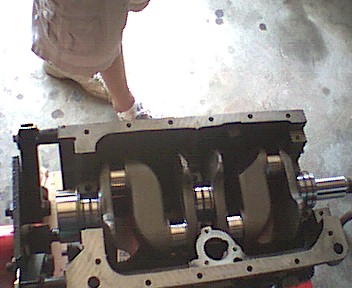
After cleaning the block, crank and main bearings, the bearings were fitted and assembly lube was generously applied. Next was the fitting of the standard thrust washers and the crankshaft installed. This picture is the crank installed in the engine. The next thing done was to install the bearings in the caps, apply assembly lube on the bearings and install and torque to 65 foot-pounds.
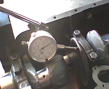
Time to check for end float. The reading was .007 and the tolerance was .004 to .008. Time for a decision. I have a set of .005 over thrust washers. If I use one standard on the inside and a .005 over on the outside (the side that receives all the wear) the end gap will be .002. I decided to do this. My reasoning was that the thrust bearing will receive pressure and will wear and bed in. When this happens the gap will expand and will be in tolerance. Note: I measured the ones that came out and they were .093, the same as the standard ones. The inside one did not have any signs of wear while the outside (facing the flywheel) had minor polishing.
Time to add pistons:
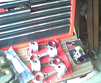
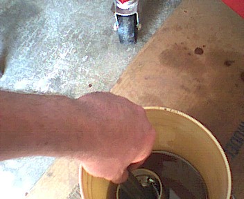
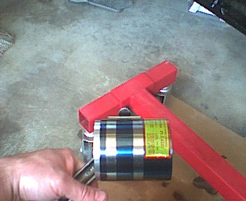
We cleaned, dried and installed all the rod bearings. Next we applied more assembly lube to the cap bearings and connecting rods bearings. It’s time to dip the pistons into the pail of engine oil to make sure they don’t scratch the cylinder wall. The rings end gaps must be properly positioned then this contraption called a ring compressor is fitted and tightened to compress the rings so they will fit into the cylinder bores. Oil is applied to the cylinder bores notice the bottle has the liquid dish detergent top on it. This must be opened so that oil flows out the tip and lubricates the bores. I used my hand to make sure the oil coated the bore, and didn’t just drip out the bottom.
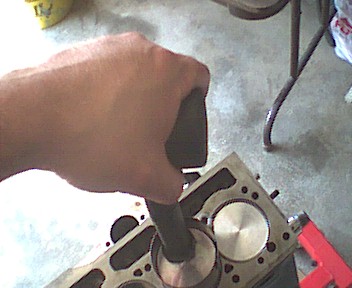
The piston is then inserted into the bore and is pushed thru the wring compressor and into the bore using a wooden or (in this case) a rubber mallet handle. Use steady even pressure and the piston will slide into the bore. If you have to force it then something is wrong and do not proceed. This is what it looks like when the piston has been properly inserted. The piston is pressed in more so that the end cap can be installed around the crank shaft. I elected to hand tighten the connecting rod bolts at this step and torque them all at the same time.
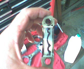
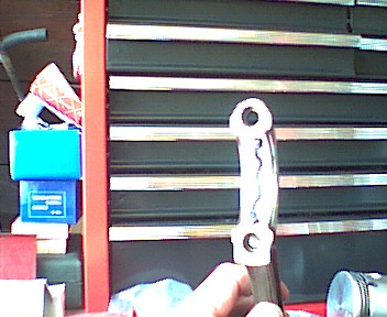
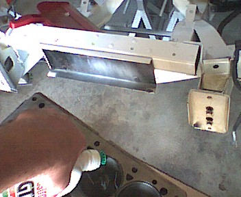
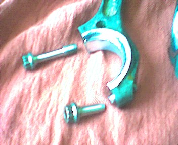
Oups, This is what happens when your torque wrench is out of calibration. The bolt on number three connecting rod just snapped. This is the head of the bolt that just snapped. I had to remove the piston assembly from the block. Here it is sitting on the bench. I had to use the Dremmel tool to cut a screwdriver slot into the broken end to remove it from the connecting rod. I’ve ordered new bolts for the connecting rods and will install them when they come in. In the meantime I’ve added the old bolts and tightened them in order to measure the gap between the top of the piston and the top of the block. I have to supply this measurement to the machine shop for them to calculate the amount of material that needs to come off the head to obtain the compression ration of 9.0:1 to 9.5:1. Measurements were as follows #1 piston .022, #2 piston .018, #3 piston .021, and #4 piston .020
Monday 6/9/02
Called Don Scinto automotive and gave them the measurements for each piston. I told them about the bolt searing and they offered to compare their torque wrench to mine to see how far off the wrench is. Their wrenches are professionally calibrated and will give a truer reading.
Friday 6/14/02
Lunchtime was spent picking up the head from the machine shop. They removed .080 from the head to get a compression ratio of 9.25:1. They had an engine that was just torqued to 45 foot-pounds on the connecting rods and 65 foot-pounds for the mains. Don set my wrench to 40 pounds and tried it on the connecting rods. Nothing. Adjusted to 35 pounds and tried, nothing. Reset it to 30 pounds and tried, nothing. Tried 30 pounds on the mains and click. This means that my wrench is measuring 35 foot-pounds light. A connecting rod bolt that should be set to 45 foot-pounds will snap at 75 foot-pounds. Lesson learned. Now I’ll have to purchase a new torque wrench or have this one professionally adjusted.
Saturday 6/15/02
The morning was spent traveling to the local Sears hardware to price new torque wrenches. They had a beam wrench for $29.99, but I wanted something a little more accurate than that. There was a Digitork wrench, but that was $99.99, a little pricey for me, after all I still have the torque wrench that has gone bad. Took a trip to the local Home Depot and found a 1 to 250 pound torque wrench with a plastic case for $59.95 which I purchased.
When I returned home from gallivanting I was surprised by a box from Summit racing. I ordered a set of ARP connecting rod bolts on Thursday and was told to expect them in on Tuesday. The plastic bag that surrounded the block for protection from durt and junk was removed and the new torque wrench was utilized to find out what torque setting the main bolts were set using the old wrench. It turned out to be 75pounds, about ten pounds more than specified. Don Scinto said that was ok, the main bolts are large enough to take that stress.
The ARP bolts come with a package of special grease to coat the bolts for proper torque. This special grease was used with the connecting rods and main bearing bolts. There’s enough left over to use with the head nuts.
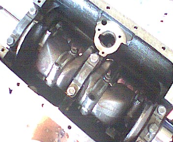
Next to go on was the front plate followed by the back oil seal housing (with new seal installed) oil pump (with new inerts) and sump. The front cover went on without a hitch and the old cam and lifters were installed. I decided to use the old cam due to cost and because the car is 23 years old and still under emission regulations and inspections. The State is revamping the whole emissions testing and no one knows for sure how the testing will be administered. Also I have to look at the original mission statement
The original plan for this project was:
1) Have a father - son project that we can work on together (so far so good).
2) Help teach my son the basic theory of automobile mechanics (he has helped a lot).
3) Do this in the least amount of capital expenditure (this is real tuff to keep focused on).
4) Wind up with a nice little reliable convertible for my wife and I to enjoy for years to come (will a new cam help enjoy the car).
I have to keep focused on these things or else I'll wind up with a small block Chevy powered spitfire that cost me $15k.
All right, I can use the old cam. Don took a look at it and gave his blessings as long as I use an electric fuel pump. The cam that operates the manual pump has a groove in it from an old pump that froze. There was a new mechanical pump installed in the car, I wonder how it was working to get fuel into the carburetors. Besides when replacing the cam you have to replace the lifters, and it’s advisable to change the valve springs.
Just put on the head, install the water pump, carburetor, and a few other things and we can put the engine back into the car. The forth of July is only 3 weeks away. I think we can get her done and on the road by then.
Sorry, Saturday started cloudy and the camera doesn’t take good pictures in the dark, it needs some sunlight thru the windows to get a decent shot. By the time the sun was out we were so enthralled in the engine rebuild that we didn’t pick up the camera.
Sunday 6/16/02
It’s Father’s day. The head was painted this morning and is waiting to dry before I touch it. My kids gave me their presents and I think it would be wiser to spend the day with them than the car.
HAPPY FATHER’S DAY TO ALL THE DAD’S OUT THERE.
Saturday 6/25/02
What ever you do, DON’T clean your red shop rags in your wife’s washing machine. My wife was out doing chores this morning and I saw that the washing machine was empty and I took this opportunity to clean my shop rags. I purchased a bag of 100 red shop towels when I started the rebuild. By this stage I have only 75 left and they are dirty and no longer usable.
I put the dirty rags into the washer along with twice the amount of recommended soap. The water turned from a cloudy sudsy color to a red mud with puddles of grease floating on top. After three cycles, I put the rags into the dryer. Note the red color kept running out of the rags. I thought that after the first washing it would stop, but I was wrong.
After putting the rags into the dryer and set it to run for 1 hour I noticed the inside of the washer was full of grease. I tried to run two more cycles of soap and water to clean the washer with no luck. Simple green got most of the rest of the visible grease out of the insides. The squeak of the kitchen door opening told me she was home and punishment was only minutes away.
I grabbed my now dry rags, threw them in a plastic bag and rushed into the garage. I was clever enough to clean the lint traps in the washer and dryer. The red lint would have given me away.
I read the book to find where I left off on rebuilding the motor. The next step was to put the new head gasket on the top of the block, replace the studs, and put the head on. The studs, washers, and nuts were easily found, thank god that I placed everything in a bag and labeled each one. I cleaned the studs and installed them into the block. The new head gasket was next followed by the head.
At this point Beverly (the Mrs.) comes into the garage. “Hi honey, I was thinking about you. I just want to let you know that I’m doing a load of your laundry.” I said “Thank you dear, that’s real nice of you”.
After cleaning the washers and nuts that secure the head I found that one washer and two nuts are missing. Looking thru all of the bags didn’t make them re appear. A quick trip to the local auto parts store came up empty. They had some 3/8 fine threaded nuts that they wanted to sell me, but they were just plain nuts, not ones designed to hold a head on an engine.
The same results were found at all the other auto stores in my area. Well I guess I’ll have to order them from a catalog. The rest of the weekend was spent on painting the rest of the things that go onto the engine.
Friday 6/28/02
I received a package of nuts and washers from Spitbits in last nights mail. It looks good to finish rebuilding the engine this weekend and maybe getting it installed next weekend.
Saturday 6/29/02
My son and I got started early this morning with installing the new head washers and nuts. After this we were able to install the push rods and rocker. We then indexed the cam by following the instructions in the Bentley manual.
The new cam gear fit nicely, but the crank gear was too small. After polishing the inside of the gear with sandpaper it fit also. The timing chain went on without a hitch but getting the cover on was another story. We wound up having my son hold the cover while I pushed the chain tensioner with a long screwdriver. The distributor gear was installed followed by the distributor.
The hardest part of the reassembly was the installation of the intake and exhaust manifolds. First the exhaust manifold was too small. I didn’t know that cast iron shrank. I wound up elongating the holes in the end of the exhaust manifold and grinding a portion that went against the intake manifold. It all went on the new studs wit a little persuasion of the rubber mallet.
The outside studs and nuts were easy to get to. The ones on the underside were another story. A socket with a swivel would not fit. The long nuts that are suppose to go on there are no longer available. A wrench would not fit. A 9/16 socket would fit but we could not get anything to turn it. We wound up cutting ¾ of an inch off a 3/8 allen wrench and grinding a 3/8 flat on two sides. This adapter would fit into the square end of the 9/16 socket and extend out enough to turn the socket with a 3/8 inch wrench. I took pictures of this but the Jr. photographer touched the camera and cleared all the photos. I’ll have to take more.
Sunday 6/30/02
Today we put on the valve cover and by trial and error installed the alternator and air pump brackets. The only things left to do is install the back plate, flywheel and new clutch assembly. We decided to take the rest of the day off and watch Boston get pounded by Atlanta.
I’ll have to stop this week and pick up some supplies for next weekend. Needed are alternator and air pump belts, a couple of oil filters, case of oil, champion spark plugs, coolant, hose clamps, and special black paint for the bumpers. In the meantime I’ll try to get some more pictures to post.
Thursday 7/4/02
Well since we were not invited to any forth of July picnics, we decided to do a little work on the spitfire. Today was spent on cleaning up and painting the front suspension and replacing all hose clamps on the engine.
Saturday 7/6/02
Friday we received in the mail the insurance card from the insurance company stating that the car is now insured. With this, the title and bill of sale we went bright and early to the Department of Motor Vehicles (DMV) to register the spitfire. I have not been to the DMV in a while and was surprised to see that they now have a concession stand where you can buy a hotdog, coke, and a hot soft pretzel while waiting to register your car.
There was only one person in line before us so our time in the DMV was short. In as little as a half hour we had plates for our baby. Now let’s get to work on getting her on the road.
Today we connected the engine to the hoist, removed the engine from the stand and lifted her on the hoist. With the back of the engine now free we put on the back cover, flywheel and new pilot bushing, clutch, pressure plate and through out bearing. After trying for the next 6 hours to connect the engine to the transmission we decided to call it a day.
Oh, I forgot to mention that around 2 o’clock my helper Eddie left, having to go to the bathroom. He came back five minutes later and informed me that the Redsox were on FOX’s game of the week. I informed him that we could either watch the Redsox’s OR put the engine back into the spitfire. He said “OK” and disappeared.
Sunday 7/7/02
It’s amazing what a night of rest will do for a stubborn situation. Within 15 minutes from starting work on the car, the engine and transmission were lined up. I grabbed the socket for the big nut on the end of the crankshaft and gave it a half of a turn and the rear tires started to lurch the car forward. I gently pushed the engine towards the transmission and she slid almost together. By strategic placement of bolts I was able to get the two bolted together. The rest of the day was spent on connecting wires and hoses together. We emptied the gas tank of all the old gas that was left from the last time it was run. Eddie stripped one of the lug nuts one of the front tires. We’ll have to go searching for one of these locally.
Things left to do:
Replace the bonnet hinge that looks twisted
Install the bonnet.
Connect all the wires that control the lights, horn, etc…
TIGHTEN THE BIG NUT ON THE CRANKSHAFT.
Add coolant to the radiator
Prime the oil pump.
Install new sparkplugs.
Paint the rear bumper to match the newly painted front bumper.
Bleed the hydraulic system and make sure the brakes work.
Start the car
Adjust the timing
GO FOR THE FIRST RIDE IN THE SPITFIRE.
Saturday 7/13/02
Today we got the following done: replaced the bent hinge, installed the bonnet, installed the front bumper and scoop, connected all the wires, tightened the big nut, added coolant, primed the oil pump, installed the sparkplugs and bled the brakes.
A Mityvac vacuum pump was purchased to bleed the brakes. This is a pretty cool tool. I did discover that you can’t just hook it up and pump until no more air comes out of the line. The pump sucks air from around the threads of the bleeder.
Another thing I discovered was the back reservoir is separated from the front on the spitfire. The front has to be totally full before it fills the back. The back reservoir fills the front calipers if anyone is wondering. I know this because as I was bleeding the brakes, I ran out of fluid in the master cylinder. Here’s how I did it. First I put the back end on jackstands and removed the rear tires.
I started the bleed process by making sure the master cylinder was full. I then attached the hose to the pass side rear bleeder and opened the bleeder and gave the vacuum pump a couple of pumps. All of this dark brown fluid came out. This color change indicates that moisture is in the system. When the fluid started running clear I would close the valve, top off the MC and move to the next bleeder. I bled the back drivers side, front pass side caliper then the drivers side caliper. when half way thru the front drivers side caliper, I heard the dreaded gurgle from the Master Cylinder. .oh no, the rear reservoir was dry. A quick stop to the auto parts store to purchase another quart of fluid and repeat the bleeding process.
Sunday 7/14/02
Today is the day that we
With my son in the drivers seat I was in position next to the distributor with the timing light hooked up. On my command he would turn the ignition to the start position while I slowly turn the distributor one way then the other. Nothing happened. I checked to make sure we were getting gas by disconnecting the fuel line next to the carburetor and placing the line into an old coffee can. Fuel was coming out (about a half teaspoon per rev.) but not in a steady stream like I'm use to with an electric fuel pump. I checked the book and it said that the mechanical fuel pump would give bursts of fuel. Note we emptied the fuel tank in the morning and added 5 gallons of fresh Sunoco 94 octane.
Next thing to check was the spark. For this operation I used an old spark plug, which I connected to the high tension wire that goes to the number one cylinder and connected the other end of the sparkplug to a good ground. We got spark. It might have been intermittent but I could not tell with the hot sunshine beating down. After a while the coil became really hot to the touch. After playing around all day we decided to give her a rest and pushed her into the garage.
Monday 7/15/02
Possible reasons that she will not start:
1) The distributor is off by 180 degreese
2) The wires are put on backwards. (the distributor runs counter clockwise)
3) She is not getting enough fuel
4) Maybe a bad ground to the electronic ignition.
I removed the distributor cap and turned the engine to around where the #1 wire was. Then by grabbing the air pump belt I was able to get the mark on the crank pulley to match up with the "0" on the timing mark indicating TDC. I removed the valve cover and looked at the valves on the number one cylinder. Both valves were closed. I was able to get a .010 feeler between the rocker and top of the valve. This indicates the distributor was in correct and not off 180 deg.
With everything back together I checked the wires to make sure that they were on properly. They were. The next step was to put some starting fluid into the engine. Since it was only me at the time I was not able to get a lot of fluid into the engine. With one hand I lifted the piston in the carb and sprayed fluid into. The butterfly in the back of the carb prevented the starting fluid from going into the intake manifold.
After spraying a small amount of starting fluid into the carb, I quickly ran around the car put my foot on the gas pedal and turned the key. I got ignition, but only one or two. I tried the procedure again and received the same results. The fuel pump might not be giving the engine enough fuel. When I had the engine apart I showed the cam to the machinist and he told me that the cam lobes looked good, but the lobe that drove the fuel pump had a grove worn into it. He was not sure if this would allow the pump to provide enough fuel and recommended installing an electric fuel pump. It's funny how memory comes back to you.
A quick trip to Pep Boys to purchase a universal inline electric fuel pump. I removed the connections for the mechanical pump and temporally connected the electric pump to see if it worked. A sudden down poor and a dead battery made us push the car into the garage hook up the battery charger and give up for the night.
Tuesday 7/16/02
We disconnected the battery from the charger and pushed her out into the driveway. I figured the battery would have enough juice from 24 hours on the charger, but after one turn of the key the thing was dead again. This was not going to stop us on our quest of getting (or at least trying to get) her going. I moved the 98 cavalier into position and using my 16 foot jumper cables gave power back to the spit battery.
I reconnected the temporary jumpers wires to the electric fuel pump and the pump started clicking. My son hopped into the drivers seat and turned the key. Nothing. Try again, nothing. Give her a little gas and try again while I moved the distributor a little counter clock wise. VROOOOMMMM.
Shouts of joy and “High Fives” came pouring out. My wife came out and said “You got he thing started, I’m impressed”.
Now to try to put the timing into order. I attached the inductive timing light to the number one cylinder high tension lead and the other wires to the battery/jumper cables. With the gun pointing towards the timing marks, I notice the mark is approximately 45-degreese before the timing marks. Trying to move it closer to the 10 degree mark only stalls the engine. I also noted that the engine is running 1200- 1500 rpm. And the book wants it to be timed to 10 degrees BTDC @ 800 +- 100 rpm
Knowing the engine will run I disconnected the jumper cables and the jumper wires to the electric fuel pump. I’ll install the electric fuel pump in the trunk after the fuel filter.
Wednesday 7/17/02
I moved the fuel pump to the trunk. I removed the panel that covers the tank and installed the pump under the tank. The fuel comes out of the tank, thru the filter and into the pump. Fuel it then pushed thru the original line to the front of the car.
With the new battery installed I went under the dash and looked for a white wire. I found one with a red stripe. With the help of my radio shack volt meter I checked the line for power. Key on, power. Key in start position, power. Key in accessory position, power. Key in off position, power???
Found another white wire and did the same with the same results. Same with the brown wire except with the off position, no power. Found a green wire with an open connector and gave that a try. Key on, power. Key in start position, power. Key in accessory position, no power. Key in off position, no power. That’s the one.
Next thing was to fish a wire from the pump to the wire in the front. I installed an inline fuse with a ten-amp fuse to the pump positive wire and ran a red wire next to the car’s harness. This wire was attached to the harness with those plastic ties every 6 inches. A short green wire with a bullet connector was pilfered from the spare car harness and soldered to the end of the pump wire.
Thursday 7/18/02
Last night I pushed the car out of the garage and tried as I could the car would not start. I pulled the fuel line next to the carburetor, attached a clear hose that I ran into a glass quart jar and ran the pump to see if she was pumping fuel. Out came fuel, but with a lot of air. Once the air was out I reconnected the line to the carburetor. By this time the coil was hot to the touch. I decided to let it cool down and give my baby a bath.
After she was clean I opened the hood, hopped into the driver’s seat and gave the key a turn. VRRROOOMM let her worm up while I played with the shift. Put her into first gear and slowly let the clutch pedal out and she moved about a foot (grin ear to ear). When she was warm enough I gave her a quick pump of the gas to get her off of fast idle.
I hooked the timing light, removed the vacuum line to the distributor, and tried to time her. I guess she didn’t like this as she bit me real HARD and died. My hair is now nice and curly with plenty of body. She was pushed back into the garage. Tonight I’ll stop on the way home and get new wires, cap and rotor.
I don’t know if anyone noticed, but I lost my $25.00 digital camera that I used to document our progress. I found it last night under the couch with dead batteries.
To be continued. . . .