
|
|
|
uC/OS-II and Real Time
Real Time Systems Real Time Systems are those in which deadlines can be met every time(Hard RT) or most of the time(Soft RT). Usually it is easier to make these with an underlying RTOS, but it is not required. Clever use of ISRs and good software development can make Hard Real Time systems without any operating system at all. However you would be reproducing much of the work that RTOS vendors do for you and severely limiting future growth of the system. Each new piece of functionality could cause reinventing another RTOS feature. So except in rare cases all Real Time Systems should use Real Time Operating Systems. |
RTOS and Real Time
Using an RTOS does not in any way guarantee a system will be Real Time. Even the most expensive and well supported RTOS used by NASA to Control rovers on Mars can miss critical deadlines if not used properly. (What really happened on Mars?) RTOSs provide services and facilitate the creation of Real Time, but only the application designer knows his deadlines and the responsibility is on him to make sure they are kept.
RTOSs Facilitate Real Time
RTOSs facilitate Real Time by providing services and managing resources Deterministically. That is everything will execute in the same amount of time or with a bounded worst case that is easily determinable. In fact many vendors publish datasheets providing the minimum, average, and maximum number of clock cycles required by each system call.
uC/OS-II The Real Time Operating System
uC/OS-II The Real Time Operating System By Jean J. Labrosse is a portable, ROMable, preemptive, real-time, multitasking kernel that can mange up to 63 tasks. The internals of uC/OS-II are described in the book "MicroC/OS-II, The Real-Time Kernel". It is written in ANSI C with a couple assembly and C language processor specific routines. Performance is comparable with many commercially available RTOSs and the execution time for nearly every service is both Deterministic and Constant. A very small and rarely used few are not, but they do have easily determinable upper bounds. On some Hardware like 8051's however a main service is Dynamic but that is not from uC/OS-II code, but because of limitations of the MCU. To have Deterministic Context Switching on 8051s you would have to fit all Tasks and ISR Stacks in the 256 bytes of Internal RAM, never swapping to external memory. Not a very Realistic scenario. Modern MCUs like Phillips XA or MicroChip PIC don't have this problem because of Mega Bytes of directly accessible memory available for Task and Interrupt Service Routine Stacks, thus no swapping of dynamically growing/shrinking Task Stacks.
uC/OSII features include:
uC/OS-II and Real Time
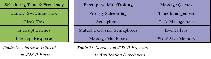
uC/OS-II helps application developers make Real Time Systems through it's Services and Characteristics. The services are MCU independent and available on all ports, but the Characteristics of each Service and uC/OS-II will be different with different Micro Controllers, Memory, Oscillator Frequencies and Porting Code. From these the Scheduling Time and Frequency, Context Switching Time, Clock Tick, Interrupt Latency, and Interrupt Response can be calculated. From these you can figure out whether particular Real Time Applications can be successful with Chosen Hardware and Porting Code. It should not be unlike Hardware Design Timing and Loading Analysis with Diagrams, Proofs, Error Margins, Et Cetera.
Characteristics
of SDCC_8031sdk_uC/OS-II
The Characteristics of SDCC_8031sdk_uC/OS-II are determined from the Hardware; 8031SDK(8032 Micro Controller, 128K by 8-bit AMD EPROM(of which only 16K is memory mapped to MCU bus addresses), 32K by 8-bit Hyundai SRAM(of which 32K is memory mapped), Harris Semi-Conductor RS-232 Transmitter/Receiver, AMD 16V8 Programmable Array Logic Device) and Porting code; os_cpu_asm.mcs51, interrupts.c, and uC/OS-II source.
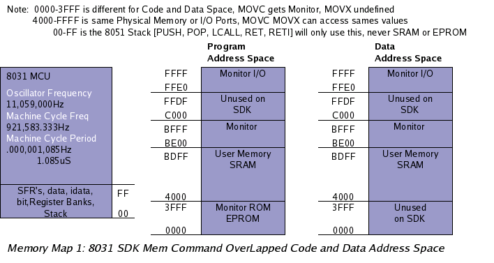
The 8032 Crystal Frequency is set at 11,059,000Hz, but it can be changed. This makes the Machine Cycle periods 1.085 micro Seconds as 12 crystal pulses are needed for one Machine Cycle. Instructions can vary from 1-4 Machine Cycles depending on their addressing and computation requirements. xdata, external RAM, SRAM accesses require 2 Machine Cycles off course because the memory is external to the Micro Controller, while local data, bit, idata, Register, and Special Function Register access only takes 1 Machine Cycle. Some mathematics instructions like MUL(multiply) can take 4 Cycles.
Scheduling Time & Frequency
Scheduling is a very important part of every Real Time Operating System, or any Operating System for that matter. It is the mechanism which decides which Task to run, and for how long Tasks will run. The uC/OS-II scheduler is pre-emptive meaning the Highest Priority Ready-to-Run Task will be made to run. It will do so until another Higher Priority Task becomes Ready, an Interrupt happens, or it gives up the MCU by Pending on a Resource or setting a Time Delay. Either way the Highest Priority Task controls it's own execution time except for Interrupts, which might enable a Higher Priority Task which would run upon completion of the ISR independent of uC/OS-II ClockTick. That is the new Higher Priority Task will not have to wait a Scheduling Frequency to run, it's Context will be switched in by OSIntExit() a required call for every uC/OS-II interfacing Interrupt Service Routine.
Two things have to be determined about Scheduling before one can know whether an RTOS Port can meet Application Timing Constraints.
Scheduling Time: the amount of time the Scheduler takes to decide which Task to run. That is the running time of OS_SchedNew() in uC/OS-II.
Scheduling Frequency: how often the Scheduler is called. That is how often OS_SchedNew() is called in uC/OS-II.
With uC/OS-II the scheduler is called every Clock Tick, every ISR(of which the ClockTick is one), every resource Signal[Post, Pend, Put, Get], and when application code calls it. The ClockTick is discussed later but usually it's period is 100 times per second(100Hz). SDCC_8031sdk_uC/OS-II Clock Tick is 100Hz. The ISRs depend on external events(sensors, ADC's, keypads, etc...), and the application code hopefully is well known to the developer.
To determine the run Time of uC/OS-II's Scheduler I have to count the Instructions and Machine Cycles per Instruction, and multiply by the Machine Cycle Period, and also hope that this Time is static or upper bound. As the uC/OS-II scheduler is a static array of pointers to TCBs(Task Control Blocks) indexed by priority, with a lookup table for finding the Highest Priority it is off course static. Probably every RTOS scheduler will be.
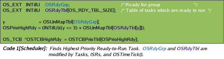
OSRdyGrp
and OSRdyTbl are the things ISRs, Tasks, or OSTimeTick(), would
modify to awaken a sleeping/Pending/Waiting Task. Typically by
making a Post/Put. OSTimeTick() obviously does so Synchronously while
the rest are Asynchronous. OSTimeTick()
is called every uC/OS-II ClockTick. The uC/OS-II ClockTick is
usually just a Timer Interrupt which calls OSTimeTick()
Synchronously.
 So
a pointer to the Highest Priority Read-to-Run Task is found in 32.55
micro Seconds regardless of Number of Tasks, System Load, or Memory
use. Also regardless of Interrupts as OS_SchedNew() is a uC/OS-II
Critical Section, meaning Interrupts are disabled during it's run
time.
So
a pointer to the Highest Priority Read-to-Run Task is found in 32.55
micro Seconds regardless of Number of Tasks, System Load, or Memory
use. Also regardless of Interrupts as OS_SchedNew() is a uC/OS-II
Critical Section, meaning Interrupts are disabled during it's run
time.
Clock Tick
In SDCC_8031sdk_uC/OS-II it is Timer2 of the 8032 chip with 16bit Auto-Reload set for 100Hz.
Context Switching Time
Context Switching Time is another important characteristic of RTOS ports. Switching from 1 Task to another is probably the 2nd most often run code after Scheduling. Also on some Hardware like 8051's it is likely the Longest Critical Section. It is for SDCC_8031sdk_uC/OS-II.
What has to be done to save one Task State and restore another is very Hardware Dependent. On some it is only a matter of saving Context Registers like Processor Status Word, Data Pointers, Accumulators, Scratch Registers, and Stack Pointers, and restoring previously saved Context Registers. After that you execute a Return from Interrupt Instruction, or possibly just a regular old Return from function call instruction and if your new Stack Pointers are right then that Return Instruction will pop an address from the new area the Stack Pointers go to and then begin executing at that address with the State set from the restored Context Registers. Maybe there will be like 15-20 Context Registers to save and restore and depending on the MCU 8-bit, 16-bit, etc... and depending on it's address bus you'll either be able to copy whole Registers at once or maybe have to make 2 copies for High and Low Bytes or High and Low Short Words(2 bytes each). So if your MCU ran at 11,059,000Hz and you had to make 2 copies for each register it would be 15*2*1.085 micro Seconds for 32.55uS Context Switches. Good! On modern Processors like PIC or PHILLIPS with enough Direct Access RAM(that is push, pop, lcall, ret, reti can use) to hold all Task Stacks this is the case. 8051 it is not however, but first the real Magic of the Stack and Historical Context, not just the current running State Registers.
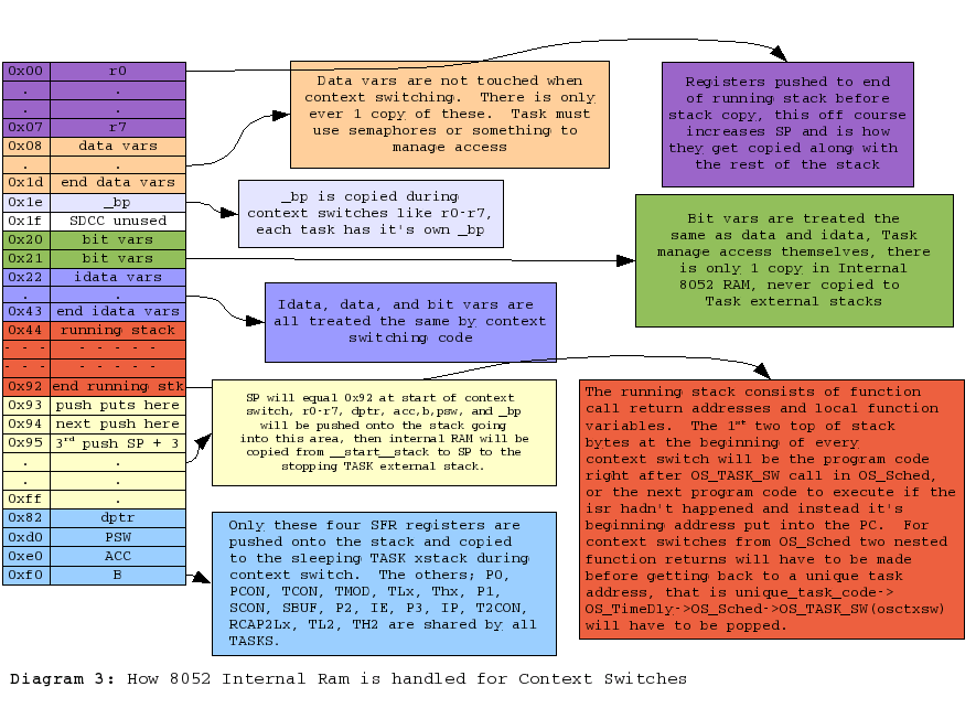
The Real Magic of Context Switching is in the Stack where unlike the Context Registers that store Running/Present State, the Historical State is saved. That is previous Function calls, Local Variables, and Return Addresses. For instance if I was just finishing OSCtxSw() in SDCC_8031sdk_uC/OS-II and RET, the last instruction was executed, the top 2 bytes would be popped of the Stack(High first, Low 2nd) and put into the Program Counter. So what? So we return to OS_Sched(). Sheeze every Context Switch returns to the same place. How do we ever get to unique code which hopefully is what our Tasks are? Well after OS_Sched() returns we get to the function that called OS_Sched() which could be in os_flag.c, os_mutex.c, os_sem.c, application code, or a lot of places. This is where and how you're getting back to unique Task code and every function return popped of the Stack with respective Local Variables makes a new Running State of Context Registers, and decreases the Historical State by 1 function call. So when you're porting uC/OS-II and you see that every Task Stack has the same values in it's top two bytes that is why. Context Switches caused by ISRs(including OSTimeTick) will have unique return addresses though, those of the code that was interrupted, so their Stack top 2 bytes will be unique(not address of OS_Sched()).
Anyway to figure out whether we can make an application work on Hardware we have to calculate the Context Switching Time. For SDCC_8031sdk_uC/OS-II it is not very good. Also implementing it is significantly more difficult then modern MCU's. This is because there is not enough Direct Access Ram to hold more then 1 Task Stack. So every Context Switch the running Task stack must be saved to external xdata SRAM, and the new Task Stack brought into Internal data RAM which is the only RAM the 8-bit Stack Pointer can reference, and the only Ram PUSH, POP, LCALL,RET,RETI and Hardware automatics will use.
Obviously
Context Switches in SDCC_8031sdk_uC/OS-II
require a lot of Instructions and they are not Static. The
running Task Stack will be different for every Task and for
individual Task at different times. All we can do is calculate the
upper bound and then hope we can make an application work with it.
uC/OS-II does allow for Schedule Locking which prevents Context
Switches and there are other tricks that can be made like setting
aside a little Internal Ram for 1 or 2 Task that don't make deep
nested function calls but running an RTOS on 8051 based Hardware is
really more an educational exercise then practical in the real world.
It is more difficult however and if you can make an app work on
8051's with an RTOS then you can certainly do it with ease on modern
MCU's.
 To
Calculate the Context Switching Time like everything else it's adding
up the Instructions and their Machine Cycles and multiplying by the
Machines Cycle Period.
To
Calculate the Context Switching Time like everything else it's adding
up the Instructions and their Machine Cycles and multiplying by the
Machines Cycle Period.
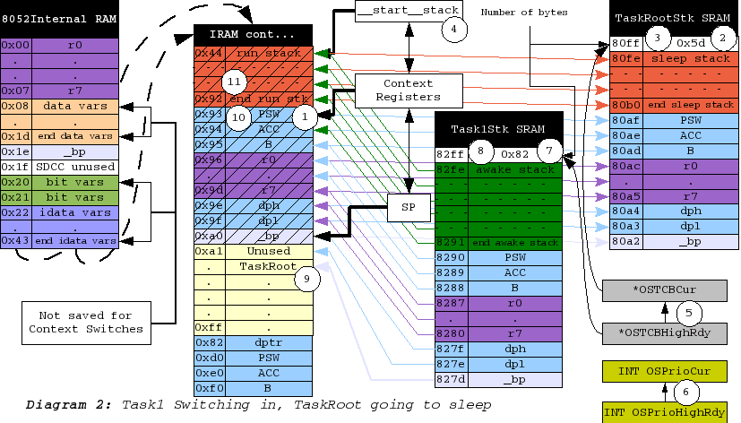
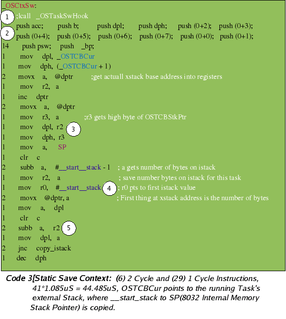
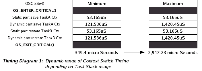
First the static part. (1) Could be a call to application developers Context Switch Hook code (2) Pushing all the Context Registers onto the 8051 stack, from which they will be copied to the current Task external stack, along with the rest of the running Stack (3) Getting the current Task xdata SRAM stack pointer into the 8051 dptr. (4) Putting the number of bytes for the running Task Stack onto that address. (5) Subtracting that amount from the dptr so that when copying you can use inc dptr and inc @R because there is no dec dptr instruction. As should be known from Diagram 2 Task grow downward in memory. Also for SDCC_8031sdk_uC/OS-II Task external Stack pointers never change their values. When Switching they are just used as a base to copy the number of running stack bytes to and from the running Stack. There is no need to ever modify an external Stack Pointer. Meaning *OSTCBStkPtr's never change. Only after Task Stacks have been copied into IRAM do their sizes change.
The Static code will take 8*2 + 33 machine cycles, or [(8*2) + 33] * 12 crystal pulses. The crystal is set to 11,059,000Hz which makes the Machine Cycle Period(12 crystal pulses) 1.085 micro Seconds. So (8*2 + 33) * 1.085 is 53.165uS for the static part of saving Task Context. It is pretty much the same for restoration, just in reverse(read pops for pushes).
 Second
the dynamic part, Copying bytes from Internal Ram to External, or
from External to Internal. With the memory layout of the Test
Application __start_stack is placed at 0x44 and theoretically could
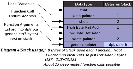
continue until 0xff for 0xbb(187 decimal) bytes to copy. This would
mean about 23 deep nested function calls if each function had 2
arguments(1 generic pointer, 1 xdata pointer), 4 local variables(2
chars, 1 data pointer, 1 short word), and the Root function had no
locals at all. So (187 - 2)/8 = 23.125.
Second
the dynamic part, Copying bytes from Internal Ram to External, or
from External to Internal. With the memory layout of the Test
Application __start_stack is placed at 0x44 and theoretically could
continue until 0xff for 0xbb(187 decimal) bytes to copy. This would
mean about 23 deep nested function calls if each function had 2
arguments(1 generic pointer, 1 xdata pointer), 4 local variables(2
chars, 1 data pointer, 1 short word), and the Root function had no
locals at all. So (187 - 2)/8 = 23.125.
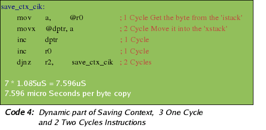
Copying 1 byte from 8051 RAM to xdata SRAM or reverse takes 7.596uS as there are 3 One cycle instructions and 2 Two Cycles. So saving or restoring Task Stacks could take as long as as 7.596uS * 187 = 1.420452 millie seconds or as short as 7.596uS * 16 = 121.536uS if you were 2 function calls deep. I do not know how to make it any clearer then this.
Clock Tick
SDCC_8031sdk_uC/OS-II ClockTick is 100Hz implemented by Timer2 ISR of the 8032 chip using Auto-Reload and as the Highest Priority ISR. The ISR Priorities are Hardware driven and independent of uC/OS-II Scheduling.
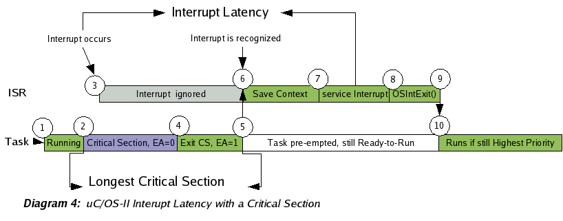
Interrupt Latency
Interrupt latency is defined as the time between the generation of an interrupt by a device and the servicing of the device which generated the interrupt. Like Scheduling and Context Switching Time it is one of the most important characteristics of RTOS ports. In fact, it could be argued that it is the most important because even if you had only 1 Task and never Scheduled or Context Switched, you'd still have to deal with Interrupt Latency.
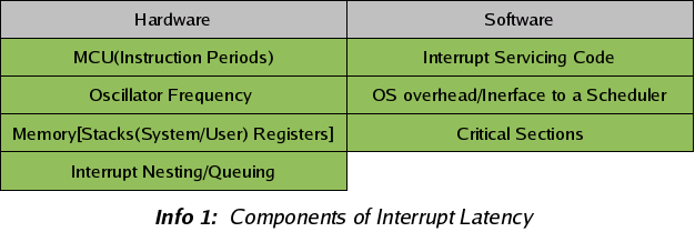
There are Two components to Interrupt Latency, (1) a Hardware Component (2) a Software Component. The Hardware Component has 4 sub components and the Software has 3.
The
first Hardware Component is off course the MCU. How often are
Interrupts checked for and how long does it take to Vector to a
Service routine. Most MCUs will check for Interrupts on the
completion of every instruction. This is the case wit the 8031sdk
and so the longest MCU time between recognizing Interrupts is the
Longest Instruction Cycle. For 8051 it is probably the Multiply
Instruction at 4 Machine Cycles, 4 * 12 Crystal Pulses. After the
Interrupt is recognized Vectoring has to happen to get to a Service
Routine. This requires saving the current Program Counter(running
code address) on a stack. For 8051 that is 2 instructions as the PC
is 2 bytes(2 Cycles). Then Interrupts of the same and lower Priority
are blocked. Copying a byte into the Interrupt Enable Register(1
Cycle). Then the Interrupt Vector address is put into the Program
Counter(2 Cycles). So 4 + 5 for 9 Machine Cycles per Interrupt
just to get to the Interrupt Service Routine.
The 2nd Hardware Component is the Oscillator Frequency. Obviously you multiply the Machine Cycles by the inverse of this(Oscillator Period) divided by the crystal pulse to get Machine Cycles, 4 on modern 8051s 12 on the 8031SDK.
The Third Hardware Component is Memory and Stacks and for modern MCUs like MicroChip PICs their will probably be separate System and User Stacks which won't effect the Vectoring Time but will effect ISR code and Software Components. 8051's have only 1 Stack.
The Fourth Hardware Component is probably the most complicated and difficult to make Deterministic Real Time analysis of. Interrupt Nesting and Queuing. Interrupt nesting happens when there are multiple Interrupts possible of different priorities. The higher priorities can Interrupt the lower, nesting on top of them until they complete, thus delaying completion of the lower and adding to their Latency. Interrupt Queuing is a backlog of Interrupts at the same priority, so that although an ISR event has happened it will not be serviced until the previous interrupts at the same priority have been. I cannot think of any hardwares that do Queuing but most do nesting. On the 8051 a serial Interrupt could have 4 ISRs(external 1 & 2, Timer's 1 & 2) nested on top of it. Off course everything is configurable and Serial can be made the Highest Priority and all Interrupts can be disabled as the first instruction of a Serial ISR but even then before this disable instruction takes place 4 ISRs could nest on top adding to the Serial ISR's Interrupt Latency. Also with Interrupt Nesting the Hardware Component of each different priorities Interrupt Latency will be different as the Highest Priorities won't have any nesting, but the lowest one will have a lot, and in between, etcetera...
All the Hardware stuff will probably be negligible compared to the software stuff though as it's a difference between 10s of micro Seconds to 100s on modern MCUs and 10s to 1000s with the 8031SDK.
The First Software Component of Interrupt Latency is the ISR code overhead. It should be minimal as good programming practices demand that you read the Sensor, ADC, or whatever as soon as possible so that more Interrupts can happen as soon as possible, but even so Registers will probably need to be pushed, stacks changed, or Register Banks Switched before you can start servicing the device. Also you might be implementing a State Machine in your ISR to make an I2C bus, or check the level of a Sensor before possibly Posting to awake a Task for further processing. Compared to the Operating System overhead and Interfacing to a Scheduler or Critical Sections though it's negligible(10 - 20 Instructions).
The Second Software Component is the Operating System overhead. Servicing ISRs will usually mean Signaling a Task for further processing of what has happened. Not always however and depending on the architecture(meaning Scheduling Time and Context Switching Time) less often or more often. The lower the ST or CS Time the more an ISR will Signal directly to a Task even if only sending bytes of a command result that could be collected locally first and then sent up when complete. E.G.
/* rest is incomplete */
of servicing ISRs is usually going to be because of the requirement of making it work with a Scheduling Mechanism and a Task that will actually use the input to do something. Meaning the ISR justs gets some input and then Signals(Post, Put) a Task to do the real processing. This is the case with uC/OS-II and probably every other Real Time Operating System. If it was not there wouldn't be much point in using the RTOS to begin with.
In uC/OS-II every time an ISR happens the current running Task Context is saved as if a Context Switch is happening. Then upon completion of the Interrupt Service Routine the Scheduler is called to see if a Higher Priority Task has been made ready to run(Possibly because of the ISR making a Post). If so the new Highest Priority Task has it's Context Switched in and is made to run(Possibly waking up from a Pend and doing something with the information the ISR has gotten and Posted to it). If not then return is made to the current Task and the Context was saved for nothing. This is exasperated further on architectures like 8051 without separate System and User Stacks, the ability to PUSH and POP multiple registers simultaneously, or even enough on chip RAM to store more then 1 Task Stack.
Why save the running Task Context before you know a Context switch is going to happen(before the Scheduler had been called)? On page 310 of "MicroC/OS-II The Real Time Kernel" Jean discusses this and mentions the person who suggested it(a satisfied uC/OS-II user contributing to the community [OPEN SOURCE]), but the main reason I believe was that it made porting to the many "20-60" MCU's uC/OS-II can be used on easier. Or rather the many compilers and compile options for the many MCU's. It is a result of having function call addresses put on the running stack if waiting until OSIntCtxSw() to save Context, but not wanting those function calls as part of the Context, that is having to offset the Stack Pointer to get rid of them. For different compilers, MCU's, and compiler options this offset will change, and apparently is was a real PITA for all parties. You want to return to the stack when the ISR happened, not the Stack after the ISR, the call to OSIntExit(), and the call to OSIntCtxSw(), along with their respective Parameters and Local Variables. You see at the end of OSCtxSw() a "ret" instruction is made. This pops the top 2 bytes of the Stack for putting into the Program Counter. If this is not the address which was left from the Interrupt Vectoring then you're not happy. It is also stranger because when not Context Switching from ISR's the return address will always be the Scheduler routines, and this could make one wonder how you get back to different Contexts. The answer is that as those scheduler routines finish the Stack will pop and pop until you get to the unique code from which they were called, possibly a Post or Pend called from you application. Anyway as can be seen from the Context Switching Time part above doing 1/2 a Switch at the beginning of every ISR is a lot on some Hardwares, but for modern ones the trade off is worth it because the CtxSw time is so much less.
The Third Software Component of Interrupt Latency is Critical Sections. Sections of code where all or some Interrupts are disabled even though not executing an Interrupt for the disabled device. This must be done when there are shared resources among ISRs and Kernel code. For instance in uC/OS-II many sections like the Scheduler, Context Switching, Event Control Block Management, Timer Management, Semaphore/Mutex Management, Event Flags, Queues, lots of stuff have all Interrupts disabled. They don't always need to be disabled. For instance if a Serial ISR only interacts with 1 Task and that Task does not use Flags then Flags wouldn't need to be a Critical Section. The Timer still would need to be however even though it's not dealing with Serial data. It would be because if it is not then you would loose consistent Timing. So much of this stuff is application dependent and there are NO strict answers. Turning everything off though is the easiest and most portable way across different Architectures and for RTOSs vendors portability is very important so things are as they are and everything will always take work and optimizations are always possible but not always worth the effort.
Critical Sections can be in application as well RTOS code. Determining them and their worst case performance will be paramount in any Real Time System.
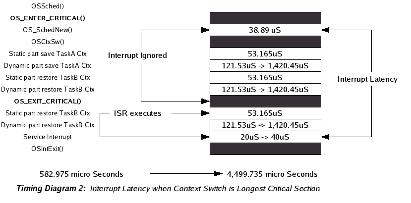
For SDCC_8031sdk_uC/OS-II the Interrupt Latency is pretty bad and it's because of the 8051 Context Switching Time. A result of having to copy in/out from external to internal RAM entire Task Stacks. As all interrupts require 1/2 of a context switch before servicing, which is a lot of instructions, SDCC_8031sdk_uC/OS-II Interrupt Latency can be incredible.
Copying 1 byte from 8051 RAM to xdata SRAM takes 7.596uS as there are 3 One cycle instructions and 2 Two Cycles. So copying the running Task Stack to external SRAM could take as long as as 7.596uS * 187 = 1.420452 millie seconds or as short as 7.596uS * 16 = 121.536uS if you were 2 function calls deep. Quite a range but still deterministic because your worst case Interrupt Latency can easily be calculated. Remember you can always get a faster crystal for certain 8051's, and many use less then 12 crystal pulses per machine cycle. As above however Saving the current Task context makes the Interrupt Latency only if your interrupts happen at the right time, that is not when running a critical section with Interrupts postponed. The longest critical section must be added to this Context Saving Time plus the actual ISR servicing code(possibly reading an Analog Digital Converter, an Infra Red sensor, the serial port, or whatever) which will most likely be irrelevant compared to the rest. ISR servicing code maybe 10 - 20 instructions if your doing things right. That is just getting whatever and then posting it to a Task for processing. With the Longest Critical Section the application programmer will have to analyze his own code to see but most likely it will be the Task Context Switching code itself, meaning you have started to switch from one Task to another, forcing the disabling of ISRs, and then an ISR happens which is ignored until Task A is replaced with Task B, then once Task B is running and ISRs are enabled the cpu vectors to the Interrupt Service Routine for that event which immediately saves Task B's Context before processing the Interrupt. So 1 static Context Saving code length, then 1 dynamic Task A running stack saving, then 1 static Task B Context Restoring code length, plus 1 dynamic Task B awakening stack restoring, plus hardware ISR vectoring(negligible really), then Task B static Context Saving code length, plus Task B dynamic running stack saving, and finally Interrupt Servicing.
And
that's why most people run RTOSs on hardware with enough Internal
Direct access Ram to hold each Task running stack, or at least
separate System and Users stacks, although with uC/OS-II just
separate System stack is not going to help because even if the
Interrupt Service Routing can use it's own Register Set, it would
still have to save the User stack to external Ram in potential of
making a higher Priority Task ready to run. MicroChip PIC 18 Series
micro Controllers have Mega Bytes of directly accessible Internal Ram
meaning no Task Stack copying, only Stack Pointer copying, the
difference between a couple of bytes to hundreds. Obviously on those
MCU's Interrupt Latency will be in the 10's of Micro Seconds.
Services uC/OS-II Provides to Application Developers
Preemptive Multitasking & Priority Scheduling
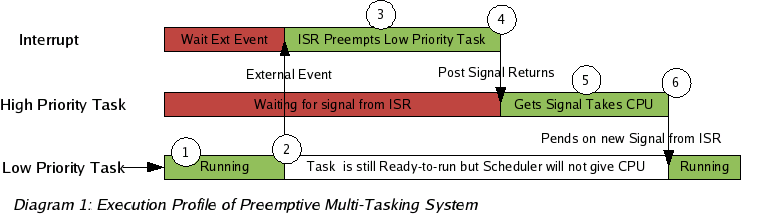
The highest priority task Ready-to-Run is always given control of the MCU. When an ISR (Interrupt Service Routine) makes a higher priority task Ready, it will be given control of the MCU as soon as all nested interrupts complete. The execution profile of a preemptive multitasking system is illustrated in Diagram 1.
Semaphores & Mutual Exclusion Semaphores
Created and managed by the application developer. Used to control access to shared resources(mutual exclusion), signal the occurrence of an event, and Task synchronization. A semaphore is a key that your code acquires in order to continue execution. If the semaphore is already in use, the requesting task is suspended until the semaphore is released by it's current owner or the requesters Timeout is exceeded. uC/OS-II offers counting and binary semaphores.
Sharing resources among Tasks can lead to Priority Inversions. Where a low priority Task is holding the semaphore a high one is trying to acquire, causing the high priority Task to wait until the lower one releases the resource, inverting the priorities of the two tasks. If another Medium Priority Task attempts to run in the interim, it will take precedence over both the Low Priority Task and the High, further exasperating the problem.
The Mutual Exclusion Semaphores of uC/OS-II were created with this in mind and use a mechanism called Priority Inheritance Priority to help application developers deal with the problems of shared resources. The Priority Inheritance Priority is set at creation time of the Mutex and should be chosen so that all Task acquiring the resource will be lower. In this way whenever a Task has the Mutex it's priority will be raised higher then any others that could be waiting.
Message Mailboxes & Queues
Mechanism for Task Communication where a Task or ISR can deposit messages(pointer's) for 1 or more others to read. Similar to Semaphores in there use and shape but having very different contents. Instead of keys the Task acquire pointers to messages. The protocol of these pointers is pre- determined at Task level according to some Task Communication protocol. The Highest Priority waiting Task will get the message. If want multiple Readers of same message, see Event Flags.
Task & Time Management
Most Real Time Systems are usually broken up in to multiple independent elements called Tasks. A Task is a simple program which competes for MCU time. With most Real-Time kernels, each task is given a priority based on its importance. These priorities are set according to a scheduling algorithm chosen by the application developer. Rate Monotonic Scheduling is often used because it can guarantee deadlines if Task execution times and periods are known. Real Time Operating systems like uC/OS-II make it possible to know Task execution Times and Periods. However RMS can not handle aperiodic events(ISRs, user input, Sensors), or shared resources. So it is just a beginning unless you periodically poll aperiodic events. All Real Time Systems will require Real Time work from developers. It should not be unlike Hardware Design Timing and Loading Analysis with Diagrams, Proofs, Error Margins, etcetera.
uC/OS-II provides all the usual Task and Time Management facilities. Creation & Deletion, Suspend & Resume, Time Delay and Priority Changes. These can be used to implement Rate Monotonic Scheduling by Delaying Task and after a certain execution, knowing that they will be woken up exactly in that time period as long as they are the Highest Priority Ready-to-Run when their Voluntary Delay is over.
Event Flags
inc...
Memory Management
inc...
| uC/OS-II(ucos-ii,ucos,ucosii) |
| Copyright © 2006 Eric Enockson |
