PPORT
1.1 :
PPort
is designed to control
the PCs parallel port.
Click here to
download PPORT
1.1.zip (239kb)
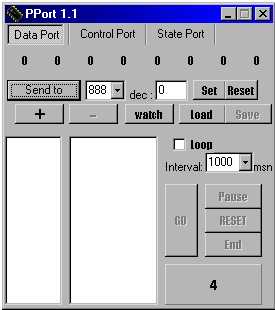 Usage
: Usage
:
-
Clicking the data
, state and control tabs at the top, you can choose the
port you want to send or receive data.
-
Change bits
,with a '0' first state value, by clicking (you can see the decimal
equivalent of the binary number.) and click the 'send
to' button.The number at the bottom of the window will
change.This shows the received data from the active port.
Also you can test
the data at the port using a multimeter.For example if you send
the value '2' (forming the bits 00000010) to the data port , you
will see 5 volts (logic 1) on the pin 3 and the other pins of
the data port ( 2,4,5,6,7,8,9) will be 0 volt (logic 0) .
Note
: On some computers
these values can be different like 3.40 volts for logic 1.The
important thing is to understand the value as logic 1.
An application
:
Take a led and connect
its anode to parallel port's second pin with a small valued resistor
if necessary.And connect the cathode to one of chassis pins of the
parallel port.( 18 to 25 ).Send '1' (00000001) to data port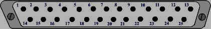
with the program.Led
will be lighted.
-
The lists
on the program can be useful when we want to send datas in rows
with a time interval.
An application
:
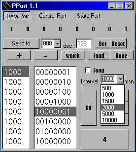
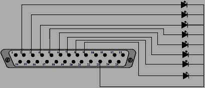 Make
these connections then make program pins decimal '1' and click '+'
button.Repeat this for the numbers 2,4,8,16,32,64,128 then click
to 'GO' button.Leds will be lighted in rows with
an interval 1 sec.You can adjust time by changing the value at the
interval. Make
these connections then make program pins decimal '1' and click '+'
button.Repeat this for the numbers 2,4,8,16,32,64,128 then click
to 'GO' button.Leds will be lighted in rows with
an interval 1 sec.You can adjust time by changing the value at the
interval.
 -
To change or remove a value from the list , you
have to choose it first.If the value you choosed is a data , change
bits to change it.To remove it click on the ' - ' button. -
To change or remove a value from the list , you
have to choose it first.If the value you choosed is a data , change
bits to change it.To remove it click on the ' - ' button.
If the value is an interval
, change the number on the interval.
Click somewhere on the
form (program window) to deselect.
-
Reset button
clears the lists.
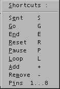 -
Right click on the form to see the shortcuts. -
Right click on the form to see the shortcuts.
-
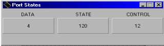
Watch button
shows an other form.This form reads the port states in every 1 m
sec.So that u can follow the changes.An example , connect a pin
of state port to a chassis pin (18 to 25).You will see that the
value '120' is changed.You can try it for control port.As you know
data port is not an input port.
 Control Port :
- Either
you can send data to control port or you can read from it.
Pins of this port are
1,14,16,17.Pin 17 is the MSB.
(MSB :Most Significant
Bit , LSB :Less Significant Bit)
Pins 1,14,17 are
inverted inside the port .For example , if you send '1' (by forming
bits as '1000' ) the MSB pin (pin 17) will be 0 volt , because it
is inverted.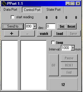
bits ( 3 -- 2 -- 1 --
0 )
pins(1*- 14*- 16 - 17*)
( * :inverted bits.)
- You can check start
reading to read data every 1 milisec.
State Port :
- State port is used
to get input only.Pins of this port are :
MSB 11*- 10 - 12 - 13
- 15 - .. - .. - .. LSB.
This port has an interesting
structure.Let me try to explain it to you:
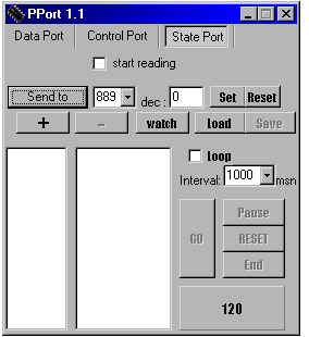
Some computers may be
different but as you see on the left , you always read '120' value
from this port...
pin 11 is called as
BUSY and this is the 7th (MSB) bit ,which is inverted inside the
port.
Pin 10 is the 6th ,pin
12 is the 5th, pin 13 is the 4th and pin 15 is the 3th bit.In addition
:
bits ( 7 - 6 - 5 - 4
- 3 )
pins ( 11*-10-12-13-15)
All pins of this port
are at 5 volts and the 2th,1th and the LSB are logic 0.But we can't
use them.
So program reads the
value 0 1 1 1 1 0 0 0 (decimal 120).
In addition , we can
control only 5 bits of this port.I suggest you to set and test this
circuit :
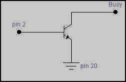 (you
can use BC238 transistor.) (you
can use BC238 transistor.)
Pin 2 is the LSB of
the data port.Busy is 5 volts.Click to watch button and send '1'
(forming the bits 00000001) to data port to make the pin 2 logic
1.With this,transistor makes the busy 0 volt by carrying it to chassis.
So that the value at
the state port will be '248' (11111000).Because busy is inverted
inside the port.
Try this circuit for
the pins 10 , 12 , 13 , 15.This will help you to understand the
behaviour of the state port.
Last , i want to give
the fundemental codes of my program,that i designed with delphi
5 :
implementation
{$R *.DFM}
procedure PortOut(IOport:word;
Value:byte); assembler;
asm
xchg ax,dx
out dx,al
end;
function PortIn(IOport:word):byte;
assembler;
asm
mov dx,ax
in al,dx
end;
Write this procedure
and function under implementation.So that you can call them from
anywhere you want in your designs.Example :
procedure
TForm1.Button1Click(sender:
TObject) ;
Begin
portout(888,2); //
888 is the decimal adress of data port.889 and 890 are
edit1.text:=inttostr(portin(888));//
the adresses of state and control port.
end;
I'm waiting for your
suggestions...
[email protected] |