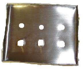
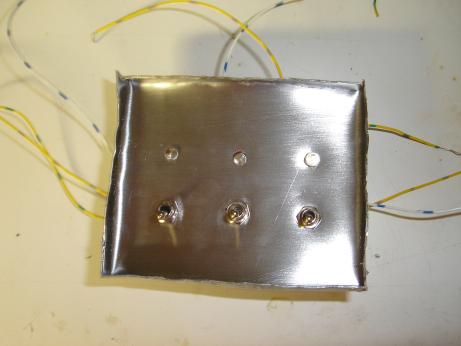
1.1.1 Take a piece of metal (9cm per 11cm for the
back , 8cm per 10cm for front)
1.1.2 Use the p200 sand paper and sand the piece
of metal, always in the same direction, this will make a nice
brushed metal look
1.1.3 If you want a chrome look,use p200 p600,
p1000 and p1500 and after use polishing paste with a cotton cloth
1.1.4 with a cutting blade and the Dremel, cut in
the corner of the part at 45° (1 centimeter (from border to
middle, not 45° 1cm).
1.1.5 Take large grip, grip the border of the
inside (1 centimeter for under the panel, 0.5 centimeter for the
front) and old them at 90°.
1.2 Plexiglas/plastic.
1.2.1 Cut some pieces of plastic:
1-7cm x 9cm
2-2cm x 7 x2
3-2cm x 9 x2
4-7.5cm x 9.5
1.2.2 with epoxy, join piece 1, 2 and 3 at 90°
to create a box with no top.
1.2.3 IF YOU WANT, you can paint the plastic.
1.3 Wood
1.3.1 cut some peace of wood:
1-7x9x0.5cm
2-2x7x0.5cm x2
3-2x9x0.5cm x2
4-7.5x9.5x0.5
1.3.2 With transparent glossy paint, paint the
wood with the transparent paint varnish the part.
1.3.3 With glue, paste each part to make a small
box with no top.
2. Now, its time to make the circuit, you have 2
choices:
-Home made circuit
-Wired circuit
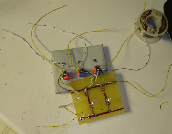
Home made fiberglass/copper circuit are not hard
to make or expensive, but here, there is not good and bad
solution. Personally i made circuit and i got some problem,
mainly, its hard to get the right position behind the front panel
and you will have to add the same number of wire anyway (but
shorter). The main problem of wire is when you made an error, its
almost impossible to fix it in the big wire ball that you will
have after connecting everything.
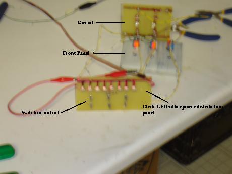
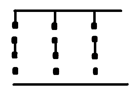
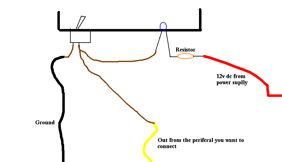
2.1.0 Circuit:
By following the getting started tutorial, make
this circuit:
2.1.1 Now, calculate the right space to add LED,
too many will not work, too few will be ugly.
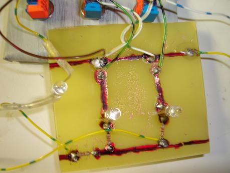
2.1.2 Now, solder resistor and LED
*
the long legs of the LED point to the resistor side, not the
ground.
2.1.3 With a 12v source, test the LED by
connecting the bottom side to negative and positive before the
resistor with a battery (9vdc)
2.1.4 Now, connect switch, first pin to
peripheral in / LED out (both), the bottom to ground.
2.2.1: wired :
2.2.2 follow this:
window3
Congratulations, your done for this part!
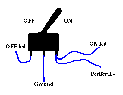
Additional tips and features:
ON and OFF LED: simply connect the wire and the
on LED to one side, the off one on the other side and the ground
on the middle. Like this:
If you want to add the panel in a CD hole, take
mesure and do it, it look like this:
-------------PNG-----------------
3.0 The front
3.1 This is easy, you just need to connect to
power switch to the wire of the old one, then add LEDs directly
on the old one, no transistor here.
*1: If you have an AT (6 years old + computer)
and you have a big ON/OFF switch, connect the relay to the old
wire (probably 4) and a 6vdc to the other part of the relay,
using this you will be able to use small on/off switch, but
sorry, no contact switch (i am looking for an issue to this).
*2: If LED of HDD/CPU don't work, use a relay for
enter 12vdc from the molex in the circuit.