Project 6 - Scratchbuilt AR15 receiver
This project is the construction of an AR15 receiver completely from scratch
and entirely on a tabletop mill.
Legal
Please read the disclaimer on the main page and note that I am not a lawyer.
According to US Federal law, it is legal for a private individual not otherwise
prohibited from owning a firearm in the US to build their own firearm. The firearm must be
a Title I firearm as outlined in the National Firearms Act of 1934 (among other things,
no automatic firearms, no sound suppressors, etc.). That still leaves a very broad array of
firearms that can be made by citizens. A serial number is not necessary as this firearm is made by
a private individual for personal use - it cannot be made with the "intent" to sell it. The BATF
recommends that the private builder put a serial number, but it is
not required by US Federal law. Only licensed manufacturers (i.e. holder of a Type 07 or Type 10
Federal Firearms License) are required by law to put a serial number on their manufactured firearms.
Note that the under US Federal law, the "receiver" is the part that is considered the
actual "firearm" - other parts like the trigger group, barrel, bolt, etc. are just pieces of metal.
State law varies in the US, but private gunmaking by citizens is legal in most US states. It is
the responsibility of the reader to check for himself. Some states may require a serial number.
Main
A company The Tannery Shop Inc
is offering a BATF-legal 80% complete AR15 receiver. The BATF has ruled
that 80% complete is not a firearm (its just a piece of metal) and can be bought/sold
without paperwork. A private individual can then legally finish the receiver for personal use.
Note that the final owner/user must be the one to finish the receiver - the work
cannot be contracted out to others. Quite a few individuals have finished their
own legal AR15's in this way.
I thought of trying the 80% complete receiver route, but felt that if I could
build an AR15 receiver from scratch on a small mill, it would make a very interesting project.
An AR15 receiver is too large to machine from a solid block on a small tabletop mill.
Machining the magazine well is going to be terribly difficult if not impossible
and there is not enough room to bore the hole for the buffer tube.
In addition, a suitably large block of aluminum will cost around $50 and making the receiver
from a block will generate a lot of machining waste.
The receiver is made of several parts bolted together. This makes it
much easier to machine on a tabletop sized mill. Another advantage of machining
it in pieces is that the design is can be easily changed to have magazine well sizes
for other chamberings like 9x19mm. It is also possible to experiment with different materials
like Delrin for lower stress areas like the magazine well sides. While a multi-piece receiver may
not be as strong as a one piece unit, the AR15 receiver does not bear the brunt of the firing stresses.
The barrel, barrel extension, bolt and bolt carrier are the parts that see the most
stress - these parts are purchased off-the-shelf. I have no plans to machine and rifle
my own barrel (well not yet, anyway ;) ;))
I started with the AR15 blueprints available for download on the AR15.com website
or Biggerhammer.net.
I have simplified and "squared off" the design of the receiver and divided it into 10 parts
that are bolted together with #6-32 button head and socket head cap screws.
To keep things simple, I have modified the design as follows:
- no bolt catch
- no winter trigger guard
- no captive pushpins for takedown - uses 1/4"-24 diameter bolts and nuts to hold upper/lower together
- front lugs squared off - cannot tilt open the upper from lower - must lift upper off to remove
- detentless safety lever - use magnets to hold lever safe/fire position instead of detents
- buffer retainer simplified - a 3/32" diameter rod (held in place with Loctite 242) is used to retain the buffer
The scratchbuilt receiver will take standard AR15 fire control parts and will have the standard magazine
release button. I have done this project entirely on a tabletop mill and the most basic
of milling machine accessories. I did not need a rotary table or other expensive fixtures. I did
have to buy a boring head to bore the hole for the buffer tube (aka receiver extension).
Each piece is relatively easily machined on a table top mill. It just takes time. If the reader
wants to use larger pieces of aluminum, the receiver can easily be built using fewer bolted pieces.
Since each part in the current design is small, it is easy to find/buy aluminum stock
to make the part - this keeps material costs low and minimizes machining waste.
I was able to find all the aluminum (basically just aluminum plates and 4 small blocks)
from a local scrapyard for around $7! The aluminum is mostly alloy 6061 which is not
as strong as the alloy 7075-T6 aluminum used in a typical AR15 receiver, but it should be OK
as I have beefed up certain areas.
After machining was completed, the pieces were degreased and bolted together. Loctite 242 ("blue")
was used to hold the machine screws in place. "Rust-Oleum" flat black paint was used to finish
the metal after a thorough sanding using a fine abrasive pad. I used a sponge brush to apply the paint.
I recommend thinning the paint first since it is a bit too thick to apply smoothly (found out the hard way!)
I put two thin coats of paint with a light sanding between coats. The finish will look "powdery" and almost
gray after sanding. Wiping the finish with Breakfree CLP will give a decent uniform black finish.
Some minor brush marks are still visible, but I can live with that. The 1/4"-24 bolts used to hold the rifle
together instead of pushpins were painted as well. I thought of home anodizing it, but since the pieces are made
from different aluminum stock, they may wind up with slightly different shades of black!
I bought an AR-15 carbine parts kit (everything except the lower receiver) from a gun show
to complete the rifle. There are several sources of such kits. I got the plain barrel with no muzzle brake since
I want the carbine to be as simple as possible.
I have made complete blueprints for the AR15 scratchbuilt receiver. They are available for free download as a single 935kbyte .pdf file. I do not have a high bandwidth server to host them, but fortunately, there are several copies on the web:
Blueprint Q&A
Some readers who are building the receiver had questions on some "missing" dimensions in the prints. Actually, all the dimensions are present but you may have to look at the dimensions of another part or sheet to figure it out. To make things clearer here are some questions and answers:
- In the "Magazine Well - Rear" print, sheet 4. How deep is that 0.250" wide cut? The "rail" itself is 0.104 "
high but the notch itself doesn't show as going all the way down. In other words, the cut out is 0.250" by 0.155" by X inches?
If you take a look at "Receiver - Left Side" sheet 3, you'll see one part that mates with the "Magazine Well - Rear" part.
The 0.25" wide channel on "Magazine Well - Rear" lines up with the slot in the "Receiver - Left Side", and the depth of cut matches as well. So the depth of cut of the 0.25" slot on "Magazine well - Rear", sheet 4 is 0.069"
- What is the center position of the 0.25" radius cut in "Grip", sheet 3?
The 0.25" radius rounds out the square corner, so the center is 0.25" in X,Y offset from the edges. The X position is 0.25+0.4=0.65" from the right edge of the part, and the Y position is (1.715-1.218)+.25"=.747" from the top. See "Grip", sheet 1 for the dimensions used to calculate these values.
- What dimension is the two crosshairs 0.2020" apart in "Magazine Well - Rear", sheet 6 trying to represent?
Those two crosshairs are showing the centers of the radii at the ends of the oval magazine release button. They do *NOT* represent the innermost hole diameter of the part, which is 0.2031" in diameter (See "Magazine Well - Rear", sheet 7,8).
Photos
I know you all want pictures so here are some of them. All these pictures are also stored in My Webshots Albums.
Please use the Webshots link to save bandwidth if you want to see all the photos (its faster too).
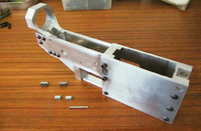
Parts-in-progress:
Assembled Receiver:
All Done:
Q&A
Since posting this, quite a few readers had questions. Here are the answers....
- What are those "small pieces" shown near the receiver photo?
There are a pair of keystock bars with some very strong rare earth magnets (Radio Shack) attached -
they are epoxied to the outside and will hold the safety lever in the fire or safe position
(no detents needed) and serve as "stops." The other pair of short square bars are guides for the
magazine catch - I found out later that the magazine sideplates are thick enough so I did not
use the guides. The short rod you see is the buffer retainer
(its 3/32" diameter) - it is held in the hole with some Loctite 242 - I thought it was easier this way.
I cut a screw slot at one end so it can be easily twisted out if needed. Also, I removed half of the
rod at the other end to form a crude "D bit" reamer to clean the hole of dried Loctite if it is
ever removed.
- Did you use a lathe to thread the buffer tube part?
No, I used a large tap. If you have access to a lathe, it would be cheaper to thread using a lathe.
- Why aren't the sideplates made of 2 large pieces instead of the 4 pieces you have?
I decided to make the mag well 2 separate pieces in case I want to make another set for other
magazine types. Also, I didn't have any pieces of aluminum plate large or thick enough.
- How much did all that aluminum cost?
I found it all at the local metal scrapyard. If I remember correctly, it cost something
like $7-8 for what I bought - I probably have enough left from that batch to build 1 or
2 more receivers.
- Hey the back of the buffer part looks flat - where is the "oval depression"?
Very observant! - the (fixed) telestock uses a "receiver end plate" with an oval bump that
mates with a similarly shaped depression in the receiver... To simplify things on mine,
I just installed the "receiver end plate" backwards (bump outside).
Just hold it in place so it does not twist while tightening and you won't have any problems.
- Why did you use socket head cap screws around the magazine release button? (all the other screws
look like button head cap screws)
I used socket head cap screws above and below the mag release so they
could be closer to the magazine release button - I wanted the screw heads to stick out more to
crudely duplicate the "anti-bump ridge" they have around the mag release button on the A2 lowers.
- What other screw sizes/types did you use?
The two screws that hold the trigger guard in place and the two screws holding
the bottom of the fire control well in place are #4-40 x 3/8" long pan head machine screws (due
to lack of space). The four screws (two on each side) near the magazine catch are #6-32 x 1/2" long
socket head cap screws. All other fasteners are #6-32 x 3/8" long button head cap screws.
- Why didn't you use the standard AR15 trigger guard part?
I could have designed the parts to use the standard trigger guard, but I felt lazy that day .... ;)
- Why do the safety/selector lever stops look so weird?
To simplify things since the walls of the receiver are just a bit too thin for the detent and spring,
I simply used magnets to hold the safety/selector lever at the end of its travel. It works pretty well.
The button head cap screws sticking up prevented me from mounting the selector in the normal position
(i.e. 'forward' for safe, 'up' for fire). In this receiver, 'backward' is 'safe', 'up' is 'fire'. This works
only because of the semi-auto style safety/selector lever. If the safety lever is ground down a bit to clear the
screw heads, the normal positions will work, but I did not bother....
- Does the whole thing work?
After assembly and before live firing,
I manually dry cycled the firearm and doubled checked that the safety, disconnector
function, trigger, and magazine catch worked. Everything checked out OK. I took it to the range
and fired 60 shots. No major problems! I had 2 failures to go into battery - had to push slightly on
the forward assist. I'll keep shooting it some more to break it in, but other than that, I am
very pleased with the scratchbuilt receiver... well on to the next project!