|
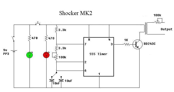
This is my latest electric shocker circuit that I have designed. The advantages with this circuit are that it has variable output current and two ranges of frequency adjustment. When the 10uF capacitor is used the frequency is variable from 15Hz to 2Hz and when the 10nf capacitor is used the frequency is variable from 2kHz to 15kHz. The green led is to show when main power is on and the red led is to show when the circuit is in operation. The transformer used can be any mains transformer with a 240 - 3v, 240 - 6v or 240 - 9v rating. The transformer is used in reverse. |
|