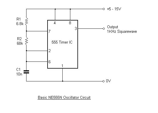
The formula for calculating the frequency is:
f=1/(0.7*(R1+(2*R2))*C1 Hz)
The values in the formula are expressed in ohms, farads, seconds and hertz.
The frequencies attainable from this circuit can range from many seconds per cycle to more than 500kHz. The capacitor can be from a few tens of picofarads to many microfarads. The resistors can have values from around 4.7k up to 10M or more. Polyester, polystyrene and silver-mica types of capacitors work best.
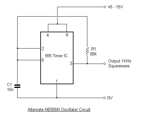
The formula for calculating the frequency is:
f=1/(1.4*R*C).
The values in the formula are expressed in ohms, farads, seconds and hertz. This formula is much simpler than that of the previous circuit. With the values shown on the circuit, the frequency is calculated as 1050Hz, but like the previous circuit, this arrangement can operate at frequencies up to around 500kHz. If the circuit uses the ICM7555 - the CMOS version of the 555 timer then the performance of the circuit is much better than if the circuit is using the bipolar type of 555 timer. The output has a near perfect 50 - 50 duty cycle. For adjustable frequency, a variable resistor can be used in series with R1 to give the required range of adjustment.