
How to Build an R/C
Mini Tank
2nd Edition
By Kyle
Liberg
Contents:
Introduction
Please note that depending on the type and
level of skills you have, this instructional could be used exactly or many
different substitutes and changes could be easily made in the design. That is
someone with good fabricating skill may only want to get some ideas from these
plans, while other people may want to follow them exactly.
These instructions are written for
someone who is new to RC and may cover a lot of information that will seem very
elementary to more the advanced hobbyists. I am also trying to be as thorough
as possible for the same reason, so don’t be intimidated by the length of the
instructions.
Be aware that the modifications to be
done to the 2 servos for this project will most certainly void any warranty on
them.
Finally, please use common sense and caution
when working with any power tools (or glues). So don’t come crying to me if you
cut off a finger or glue your hands together.
Materials and Tools
Explanation
Parts and other
materials:
Chassis
Material- In theory you can really build the chassis from anything you
want. If you had the money you could built it from 24K gold if you wanted to.
I used plexi-glass (also know as acrylic glass
or plastic) for my first and second models, because I liked the look of it. For
this (third) model I used wood since it’s a lot easier to work with. The choice
is entirely yours, though. Just be certain what ever material you choose, you
have the tools and skill to work with it.
As far as the thickness of the material goes,
it should be a ¼ of an inch. A 2 foot by 2 foot sheet will provide more than
enough material. If you can find a smaller piece, a 1 foot by 1 foot should
also provide enough material (and extra for any mistakes).
Now is the question of where to find the
material for the chassis. Places like Menards or Home Depot should be able to
offer you a good selection of both wood and plexi-glass sheets. Hobby shops
also sometimes carry a selection of thin plywood, but expect to pay more for a
smaller piece.
Glue- You will need glue
for holding together the parts of the chassis. For wood there are many types of
glue that will work well. I know that Elmer’s Probond works very well, but
there are plenty of other good choices out there too.
For the plexi-glass chassis on my first two
tanks I used Devcon’s Two Ton Epoxy. Like-wise there are also many other glues
out there that would bond plexi-glass equally well.
If you’re not sure whether a certain glue will
work with your selected material, just take some small pieces of scrap and test
glue them to see how well they hold.
Tamiya’s
Tracked Vehicle Kit- This kit from Tamiya’s educational series will obviously
provide a lot of vital parts. You can find it at places like Tower Hobbies or
your local hobby shop. I know that Edmund Scientifics carries it too (they
charge more). You can Googe “Tamiya tracked vehicle chassis” too, to find more
places that sell it.
A radio
system- If you don’t already have a radio, receiver, and two servos
you will need a system that has all of those. I would recommend a Futaba AM
system. Other brand systems would work fine too, so long as they are for
surface vehicles. For this purpose I would also recommend it being a two stick
radio, opposed to a pistol style radio. You certainly can use a pistol style if
you want (I use one with mine), but the stick controller would be a little
better suited for the driving style a tank requires. Here are some good, base
level systems (see More Information on Radio Systems
for an explanation of terms):
·
Futaba 2DR AM radio
·
HiTec Aggressor Ranger 2N
·
Airtronics Avenger AV2X
Batteries
for the Radio System- In order to run both the transmitting and receiving
parts of the radio system, you will of course need batteries. AA alkaline
batteries will work fine, but rechargeable replacements will save you money in
the long run.
Fasteners- Many parts of the
tank need screws to attach them to other parts. Most of the screws you need
will come with the tracked vehicle kit or the servos. You will get 8 additional
#2 by 3/8 inch sheet metal screws. I used hex heads, but these also come in a
Phillips head type too. If the servos you are using don’t have screws with them
for what ever reason, you will need 8 more screws of the same size.
If you would like to make a body or a
lid for the tank, you will also need something to fasten that down too. For
quick access to the batteries, I would recommend using some strips of adhesive
backed Velcro. You can find it at many craft and sewing stores such as Hobby
Lobby. Small screws will work too, but will make it slower to open the tank up.
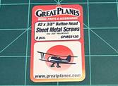
You will need:
Eight #2 x 3/8” sheet
metal screws
(16 if your servos
don’t have screws with them)
Internal antenna wrap- You need something
to hold the antenna wire of the receiver. Something like a piece of cardboard
or plastic will work fine. For mine I used the back panel of the package the
above screws came in.
Optional
Materials:
Paint- If you like, you can
paint your tank. Make sure that the paint will stick to the material you
choose, be it wood or plexi-glass.
Double sided tape- Not to be confused
with servo tape. This is like ordinary scotch tape, yet both sides of it are
sticky. You can find it at many office supply stores, greeting card outlets,
and other stores that carry stationary type materials. It’s very useful for
holding parts together temporarily for cutting out identical parts.
Servo tape- Having some of this to
secure some of the parts in the tank would be a very good idea, but technically
not necessary. You can find servo tape at hobby shops that carry RC stuff.
Adhesive Velcro
strips- This
would be good for securing a lid on the tank, or holding the batteries in
place. Anything you want to stick down, but be able to remove quickly later.
You can find this stuff at many arts and craft type stores such as Hobby Lobby.
Extra material and
fasteners for a body or a lid- You may want extra material for making a
body, or just a lid. You’ll also need some sort of fastener to hold it on,
whether Velcro or screws.
Saw- You will naturally
need something to cut out the parts with. A power saw is nice to have, but a
hand saw will work fine too. Make sure the blade type (teeth per inch number) and
cutting speed are suited to the material you’re using. Plastics tend to melt at
the high speeds many wood saws operate at.
A drill and set of
bits-
There are 16 holes that need to be made in the chassis, so having a range of
small sized drill bits and drill to use them is necessary. You could even use a
simple hand chuck for making the holes. That’s all I used for the 8 screw holes
that hold the servos. Dremel offers a nice set that has all the sizes you’ll
need and more for about $6.
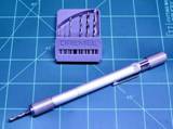
You will need at
least:
3/32 inch
1/8 inch
Having
one larger bit (1/4 inch or larger) would also be good for removing material on
the drive wheels.
Sandpaper- This will come in
handy for smoothing out any rough edges on parts or enlarging holes gradually.
If you use plexi-glass it is a good idea to rough up gluing surfaces for better
strength.
An accurate ruler- It should have lines
on it that mark at least 1/16 of an inch. Try to mark and cut everything as
accurate as you can.
Something to mark cuts
with- Just
a plain old #2 pencil will work if you’re using wood as your chassis material.
For plexi-glass or other types of plastics, a hobby knife (x-acto knife) or
sharp scribe will work better. Running a pencil over a scribe mark on plastic
will help to make the line more visible still.
Optional
tools:
Rotary tool (Dremel) - These come in very
handy for a lot building projects. With the wide variety of attachments
available for them, you could literally build the entire tank with this tool
alone. There are even attachments that will turn one into a mini saber saw.
For this project it would be
particularly helpful for shortening hub screws (with a metal cutoff wheel) and
making a recess in the back panel for the servos (with a router bit and
attachment). This is an entirely optional tool, though.
Mini Square- This would be useful
for making sure parts cut and glued at accurate 90 degree angles.
Let’s Begin
When it comes right down to it there are only
three main components to be built. First of course is the chassis for the tank.
That’s basically just a box with some holes and slots in it. Second are the
modifications to the servos to make them act as gear boxes instead of limited
travel arms. Last are the drive hubs which attach to the servos. All the rest
of the work is just putting existing together and adjusting them to fit.
Part Dimensions:
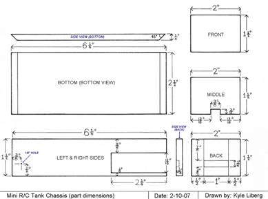
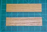
Left and
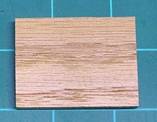
Right Sides (mirror dimensions of each other):
Both sides start out as rectangles that are 6
and 1/4 inches long by 1 and 1/2 inches tall. Once both rectangles are the
proper size it would be a good idea to stick them together with double sided
tape to make the next few cuts at the same time. Make sure the pieces are lined
up straight before they get stuck together.
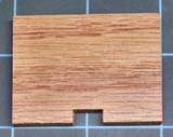
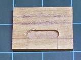
Now you are going to cut out a long slot at
the back for the servo to fit into. The slot in the back needs to be 13/16 of an
inch wide by 2 and ¼ inch long. It needs to be 1/8 of an inch up from the
bottom. Once the slot is cut, make sure it is big enough by sliding one of your
servos into it. If it doesn’t quite fit you can take some sandpaper or a file
to carefully enlarge the slot. Don’t worry if the slot looks a little too long
(or tall), this will allow you to make some slight adjustments of the servo to
adjust track tension.
Next a 1/8 inch hole needs to be made ½ an
inch up from the bottom and 3/8 of an inch in from the front. This will be
where the front axle goes.
Bottom
Piece:
With the sides completed we now come to the
bottom piece of the tank. The bottom needs to be 6 and ¼ inches long by 2 and
1/2 inches wide. After you have cut out a rectangle to these dimensions, you
may want to cut the front and back edges at a 45 degree angle to increase
clearance. The bottom edge will be shortened, but the top should remain 6 and ¼
inches from end to end. Making these angles is optional, though.
Now one last thing needs to be done to the
bottom piece. There needs to be four 3/32 inch holes drilled into so the road
wheel brackets can be attached with screws. To mark the location of these holes
you simply take the bracket (the grey plastic piece with five holes on one side
and two on the other) and center it on the bottom, keeping it flush with the
edge. Now take your pencil and trace the two holes where the screws will go.
Take the plate off and drill the 3/32 inch holes at the center of the circles
you just made. Repeat for the other side.
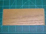
Front,
Back, and Middle Panels:
All you’ve got to do now is cut out some
rectangles for the front, back and middle of the chassis. The parts should all
end up being 2 inches wide by 1 and ½ inches tall. The front piece is just a
plain 2 inch by 1 and ½ inch rectangle.
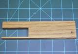
The piece to be placed in the middle is the
same size as the front (2 x 1 ½), but needs a small slot made at the bottom
(for the servo wires to go through). It should be center from left to right and
is 3/8 of an inch wide by 3/16 of an inch tall. This should be the right size
for the servo wires (and plugs) to fit through.
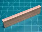
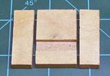
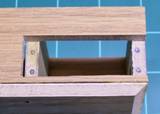
The panel that goes into the back needs to
have a recess made in it so that the servos fit right. There are several ways
to do this.
The first way is to build it from three
separate pieces. All you need to make it this way is a saw. Cut two pieces 1½
inches by ½ of an inch. Cut the third piece 1½ inches by 1 inch. This third
piece will be the one the slot is cut into. The slot will be ¼ of an inch wide
by 1/8 of an inch deep. Start by making a cut 3/8 of an inch up from the bottom
and continue to make 1/8 of an inch deep cuts until the slot it ¼ of an inch
wide.
Once all three parts are made, glue them all
together so that they measure the same size as the front and middle panels (1 ½
inches tall by 2 inches wide). Place them on flat surface to thoroughly dry. If
you place a piece of wax paper under it, you can avoid gluing the part to your
workbench.
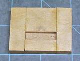
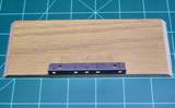
The other way to make this slot is to take a
small router or adapted rotary tool and simply make a 1 inch by ¼ inch wide by
1/8 inch deep slot in the piece. This slot will be 3/8 of an inch up from the
bottom and ½ inch in from both sides.
Assembly of the
Chassis
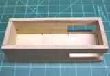
Now that all the pieces for the chassis
have been cut out, it’s time to assemble them to form the chassis of the tank. Take
the bottom, left and right sides, and the front and back pieces (the plain
piece and the piece with a recess in it). DON’T glue the middle section in
place yet! First set them next to each other on the bottom piece to make sure
they all fit together. After you’re sure that the pieces are the right size you
can glue them together, making sure they are set as flush as square as
possible. Using clamps or weights to hold the pieces together while the glue
dries is a good idea.
After the glue has thoroughly dried,
you can now take you servos and the middle chassis piece and find the proper
location for it to be glued. Push one of your servos into the side slots and
then insert the middle piece in front of it. Adjust the servo so that edge of
the back tab is flush with the back of chassis. Now move the middle section
forward or back so that the edge of the front tab is lined up with the front of
the piece.
Once you sure the middle piece is in a good
position, you can mark the location, pull the servo out and mark the same
distance on the other side. Now glue the middle section in place at the
locations you marked, making sure that it sits straight left and right as well
as up and down (square with the bottom).
Wait for this piece to dry before
drilling the holes for the screws.
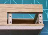
Holes for Attaching
Servos
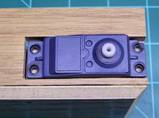
Now
all we need to do to the chassis is make some holes into the sides of the
middle and back pieces to put screws into. Take your servo and slide it into
the slot in the side. In order to put the servo in you may need to tilt it slightly
(wire side going in first). Hopefully the tabs will still line up with the
edges of the middle and back sections. Now mark the location of the holes in
the tabs and pull the servo out again.
Now you have a good idea of where the
screw holes need to be placed. If the holes don’t quite sit center (left and
right) on the edge, try to move them over a bit so they do sit center. The
holes in the tabs should be large enough to allow for a little movement of the
small screws. You will want to avoid splitting the wood, so keeping as much
material on both sides of the hole is a good idea.
Once you’re sure that the holes are
marked right, you can drill the holes. They need to be ½ of an inch deep and
3/32 of an inch in diameter. Drilling a smaller hole first (called a pilot
hole) is also a good idea to help keep the hole straight and avoid splitting
the wood.
Once all holes are the right size, you can
take four screws that came with the servos and test fit one of the servos.
Don’t over tighten the screws! They only need to be lightly snug.
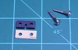
Making
Shims
Now to get both servos to fit in at the same
time you’ll need some shims. There should be one set (four total) of rubber
shims that come with the servos. You just need to make one more set of four
shims to put the servos a little farther apart. I made these shims out of a
popsicle stick. Any other material that it about 1/8 of an inch thick will work
too. They need about the same size as the tabs that are on the servos. You
could simply trace around the tab to get the size of the shim and location of
the holes in it.
Now that you have a
chassis to put them on, you can modify the servos to work the way you need. To
make the servos turn all the way around, two parts need to be cut off. First,
of course, you need to open up the servos to get at the parts inside.
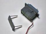
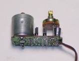
Taking the top cover off you should see a
bunch of little gears that connect from a little motor and wind their way to
the output shaft. It would be a very good idea now to take notes as to where
all the gears go.
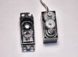
If you take the output shaft, you should see a
little notch sticking out of the side in between the spline and the gear. This
is a stopper that allows the output shaft to only turn a limited distance. This
needs to be cut off as flush with the shaft as possible.
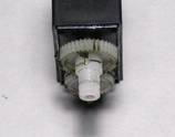
Now, looking under the output shaft,
we see a little knob sticking up (brass on Futaba, plastic on Hitec). This is
the pot (or potentiometer), which tells the servo when it has reached the right
point. This knob needs to be cut off as low as possible with out damaging any
other parts. With some servos (standard Futaba servos are like this) it is
possible to push the circuit board out from the center piece of the case, and
easily cut the knob off plenty short. Other brands (like Hitec) have the motor
and pot glued into the case, and thus are harder to cut down.
Once the pot is cut down to the point it no
longer can be moved by the output shaft, set the pot to a good mid point. You
can just feel the travel and estimate where the center should be, or you can
connect the servo to a receiver and battery to find a point where the motor
stops running. Don’t forget to center your radio trims before adjusting the
servo pot neutral point.
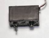
Once that is set you can put the servo
back together. You did make notes as to where the gears go, didn’t you? Repeat
the process for the other servo.
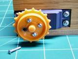
Now that we have a chassis and drive line, we
just need to put on the drive wheels. We need hubs to mount the drive sprockets
on, and if you bought two new servos for this project, then you should have all
the parts you need to make them.
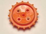
First cut off the tube that sticks out
of the center of the drive sprocket. You want it as flush with the inside of
the wheel rim as possible. You can take a large drill bit to remove that last
bit of orange plastic shaft that can’t be reached with a saw. Don’t drill too
deep; you just want a fairly flat surface on the inside of the drive wheel.
Now it’s time to make the hub out of
the servo arms. If you’re using a Futaba servo and arm, you will use the four
armed horn. Each of the four arms needs to be shortened so that only the l hole
remains. Leave as much material as possible.
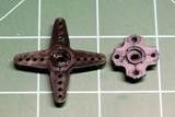
If you’re using a HiTec servo, you will be
using the round servo horns that should come with those. No cutting needs to be
done on these; you just need to find the holes that best line up with the holes
on the drive wheel. The fit on these horns is not quite as good as the Futaba,
but should still work. Two of the holes will be slightly closer together and
the other two should be a little apart. Regardless, the larger holes on the
drive wheel should allow for that horn to work.
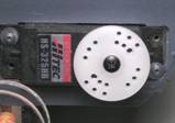
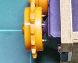
Take the servo horn and attach it to the servo
using the screw supplied with it. Don’t over tighten the screw.
Now to attach the drive wheels to hubs. For
this #2 size sheet metal screws should work very well. Ones that are 3/8 of an
inch should not need any shortening (they come pretty close, though).
Shortening the screws with a rotary tool, grinder, or other similar tool would
look nicer, but is not necessary.
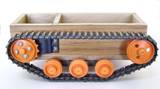
Assembling the Parts
on the Chassis
Now that all custom part have been built all that’s
left to do is to put all the components on the chassis.
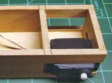
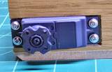
First
put the servos in the back, making sure to feed the wires on them through the
slot in the middle section before putting the servos into the slots and
screwing them in place. Don’t forget to put the shims in place too.
Next
you’ll just assemble the tank in the same way you would with the kit, just
using the new chassis to attach the components.
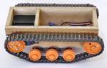
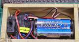
Once
the wheels and tracks are on you can put the receiver, battery, and switch in
the front compartment. Since you’re anxious to give it a test drive, you can
just set these parts inside for the time being. Later you will probably want to
servo tape the receiver and switch in place to keep this area tidy and secure.
A strip of adhesive Velcro could be used to hold the battery in place. You can
find servo tape at any hobby stores that carry RC stuff, and the Velcro strips
at sewing and craft stores like Hobby Lobby.
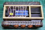
Making an Internal
Antenna
All
that’s left to do is to find a way of holding the antenna. What I used for making
an internal antenna is the back side of the plastic package the sheet metal
screws came in. I cut it off at the hinge and made a few evenly spaced holes
(14) in the lip around it to feed the antenna wire through.
Finishing Touches
If you like, you can add more parts to your
tank to make it look nicer. Having a lid and or body for the tank is not
completely necessary, but will help to dirt and debris out of the tank. Again,
Velcro can be a good way to secure a lid or body. Painting the tank is another
option. You can put as much or as little detail into it as you like.
Help and more
Information on RC:
For any questions concerning the project,
please feel free to e-mail me at [email protected]. I’ll try to answer your
questions as soon, and as best as I can. You can also find help and more
information on RC vehicles, on the bulletin boards at http://www.rcuniverse.com.
There are many, many people on the boards that are willing to help.