Why?
It happens that when you are a kid you dream about many things you can’t really afford. One of those things in my case was a telescope. I do recall my interest in astronomy when I was eight to twelve and apart from the general reading about the subject, I did make a feeble attempt to grind my own mirror which was discarded some 30 minutes after starting – grinding a quarter inch thick plate glass with an emery block was a no starter anyway. But the intention was always there … I am now a bit wiser (I hope to think) and possibly more resourceful. A colleague of mine at work some months ago mentioned to me that he purchased an 8" reflector and it triggered my childhood aspirations and was the initiator of the whole process detailed below. Apart from that, I needed my annual ‘project’ as well as some stress therapy. So, why not?
Why publish this page
It's really to acknowledge all the excellent resources made available by all the ATMers on the web. It's clear that the community of telescope builders are all eager to share experiences and provide help unselfishly. It's also my humble contribution to maybe increase the ATM experience on the web. As you will see, I have skipped most issues which are explained readily and better elsewhere on the web and concentrated on those areas where, in my opinion, are less common. This is mainly the construction of the equatorial mount using no special tools and providing some of the more 'advanced' features like slow motion control. The page also details how the finderscope is constructed as well as some notes on crosshair construction which included a polar alignment crosshair design. I am in no way an experienced ATMer and do not consider myself as an amatuer astronomer, so any comments as to how to improve the contents of this document or any criticism (constructive or destructive) is welcome.
Building or buying?
It’s all a matter of inclination and what one wants to achieve. I particularly like the notion of building the scope from scratch and all the research required to make the telescope. I do admit that the process of building the scope was the more satisfying than the actual seeing, but I’m seeing to it to make the seeing more challenging and enjoyable. In terms of time, you’d be better off buying a ready made scope; materials-wise, things might also add up as well, but the temptation of building a working scope from scratch and seeing that it works was too great to miss, so that’s that for buying or building, in my case at least.
The challenges
I set some basic criteria in the process. These were mainly:
Buying the optics
Researching the web on methods of mirror grinding made me aware of the considerable efforts required to obtain good optical results, as well as the stamina required to grind your own mirror. I decided to purchase the optics and some other basic components. I opted to purchase the following:
As for suppliers, I eventually purchased all materials from Orion Optics f the UK (www.orionoptics.co.uk). I tried a couple of other suppliers before that, namely Coulter Optical (www.e-scopes.cc), University Optics (www.universityoptics.com) and others, however, being in Europe, I decided to go for Orion Optics. I spent quite some time looking through prices and looking for suppliers. What I did was a list of components for an (initial) 8" system and plugged in all the prices from the various suppliers in a spreadsheet and compared the various merits of these. Some other constraints were that I needed to purchase through the web (to avoid mail/correspondence delay) and that delivery should be fast (hence the preference for a European supplier). I must mention that US sources are more numerous than European ones and this was a nuisance as freight, delay and risk of breakage increase in proportion to the transport distance. I found a lot of help from many ATM sites and filtered the ‘reputable’ suppliers to the following:
| SUPPLIER | WEB SITE | COMMENTS |
| Orion Telescopes and Binoculars | http://www.telescope.com/ | recommended by Dobson |
| E-Scopes | http://www.e-scopes.cc/ | recommended by Dobson |
| SCS astro UK | http://www.scsastro.co.uk/ | expensive, but has good range incl mirrors, 8" f6 Stg 169 |
| University Optics | http://www.universityoptics.com | good mirrors and accessories |
| Diffusion AstroNature | http://www.aei.ca/~astronat/dan.htm | mirrors and accessories |
| Scopetronix | http://www.scopetronics.com/atmmirrors.htm | 10" mirrors at US$329. Good pricing |
| Stellarviews | http://www.stellarviews.com | Meade mirrors, good prices, eg: 8" f6 $200 |
| Orion Optics - UK | http://www.orionoptics.co.uk | good mirrors and accessories, good range of products |
Table 1 – List of Suppliers
Another obvious requirement to keep costs down was to find a supplier who can supply ALL the materials required so I had to compromise between completeness, price and availability. Table 2 shows the price comparison between the various suppliers for the same components. Same as much as possible since not all sites had all the details.
| 8" Mirror system | |||||||||
| Mirror set | Eyepiece1 | Eyepiece2 | Barlow | Tot Optics | Focusser | Spider | TOTAL US$ | ||
| Scopetronix | 187.95 |
42.95 |
52.95 |
42.95 |
326.80 |
59.95 |
18.00 |
404.75 |
|
| E-Scopes | 234.95 |
29.95 |
39.95 |
59.95 |
364.80 |
39.95 |
39.95 |
444.70 |
|
| Stellarviews | 249.90 |
49.95 |
49.95 |
59.95 |
409.75 |
179.00 |
n/a |
588.75 |
|
| SCS Astro UK | 274.19 |
130.53 |
129.00 |
59.95 |
593.68 |
80.65 |
64.52 |
738.85 |
|
| University Optics | 279.90 |
57.95 |
55.95 |
79.95 |
473.75 |
65.95 |
31.95 |
571.65 |
|
| Orion UK | 323.53 |
90.59 |
107.84 |
70.46 |
592.42 |
41.70 |
25.88 |
660.00 |
|
Table 2 – 8" optical system component comparative pricing
Some of the suppliers contacted did not export to Malta and others did not have all the equipment in stock. I eventually settled for E-Scopes US and Orion UK. Although the timing of the procurement wasn’t ideal (it was beginning December 2001 and I wanted the goods by Xmas!), E-Scopes were not as responsive as Orion UK. I liked the service provided by the latter and eventually placed the order over the net to this company. Important consideration for suppliers: put in as much detail as possible on the site and make it as friendly as possible; this surely helped in selecting E-scopes and Orion UK.
Going for a 10 incher
One last minute revelation – Orion UK prices included VAT at 17.5% for UK orders. Since I was ordering from Malta (outside UK) I was entitled for a 17.5% reduction in prices (no VAT payable for exports outside UK to Malta). Having settled in my mind a budget of some US$700, I left this budget but opted for a 10 inch system instead of the 8 inch. I’ve got my doubts about the wisdom of this decision, more on this later!
I placed the order with Orion optics after making sure that the optics were insured for breakages (Orion included this in the price) and received the items by UPS. I have to admit that I was pretty excited to get my hands on the optics and actually feel what they looked like! By the time I received the optics, I had most of the mount ready, so the timing wasn’t so bad. Some pleasant surprises from Orion included receiving an aluminium Crayford type focusser instead of the plastic one ordered, receiving a super plossl 26mm eyepiece instead of the kellner type ordered. All at the same prices – I can’t really complain about the service.
Telescope dimensioning
I read a lot about how reflectors are designed, all reading was done on the net. Extremely helpful sites are available; too much to list, but a www.google.com search on ATM reveals all. The first document I’ve gone through which gives a good background on basic ATM is John Dobson’s manual (http://www.sidewalkastronomers.com/misc/telescopes.html). One common discouragement from virtually all these sites is to treat magnification issues with care. Although well aware of this, I still went for a maximum usable magnification of x500 (It’s so difficult to resist!!!). In hindsight, I fully agree with these ‘discouragements’ but then again, some (I) learn by experience!
Dimensions of components ordered:
Mirror aperture: 250 mm, F6.3
Eyepieces: 6.3mm, 26mm
Barlow: x 2
That would give me the following range of magnifications:
| Eyepriece combination | Magnification |
| 26mm | 62 |
| 26mm + 2x Barlow | 124 |
| 6.3mm | 254 |
| 6.3mm + 2x Barlow | 508 |
The 6.3mm eyepiece has a little eye relief and the high magnifications offered by this eyepiece is badly affected by the size induced problems of the 10" telescope. I’ll have to get an intermediate eyepiece like a 12mm one to fill the 124 to 254 magnification gap. I think this is one of the ‘usable’ magnification range, even with this size of telescope.
The length of the scope would be some 63 inches but I though this would be ok. I also looked for good quality optics, especially the mirror and I think the one supplied by Orion is not bad. It’s protection coated and has less than 1/8 wave accuracy. The flat is also matched to the mirror.
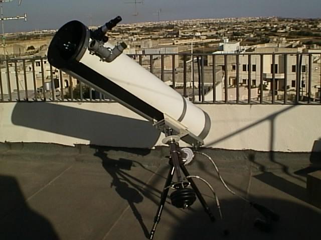
Dobsonian or Equatorial?
The million dollar question! I was going to settle for a Dobsonian at first but the (bigger IMO) challenge of building an equatorial was too much to ignore. The ease of tracking and other flexibility issues provided by an equatorial mount (like suitability for astrophotography, autotracking, etc) also helped in me settling for the equatorial design. Some lookups about the way stellar view moved as well as basic astronomy were required to get some background on the equatorial design. The theory is quite straightforward – you basically want the telescope axis to follow a conical path to track a celestial object. The ‘cone’ axis needs to be perfectly aligned to the celestial north and by moving the scope along the ‘cone’ one can follow celestial objects. Mind you, this is easier said than done as the accuracy of the equatorial mount required is quite a challenge.
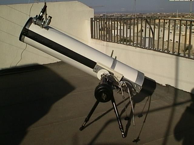
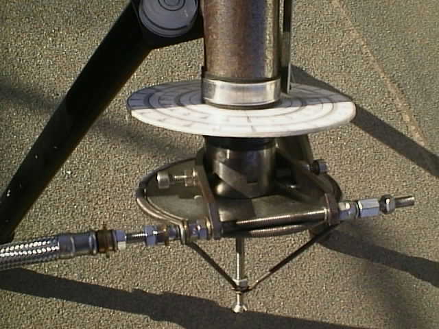
The equatorial mount
In its basic form, an equatorial mount consists of two shafts set perpendicular to each other. Other components obviously make the mount and these can be summarised as follows:
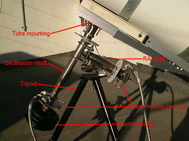
The first attempt at the shafts were going to be based on plumbing pipes fitted with bearings and mounted with a plate. These would be mounted together. The lack of exact pipe diameter to bearing inner diameter availability as well as the ‘prohibitive’ costs of new bearings (some US$15 per bearing and I would need 4 of these) put me to think about alternative solutions. A visit to the local automobile scrap yard soon proved inspiring and for US$5 I got my hands on 5 used automotive steering columns. These steering columns had most of the required components included – complete shafts with bearings!!! I decided to use the Honda Civic and Fiat Ritmo steering columns and use the rest for the ancillary equipment. As it turned out, between these two columns, I obtained the following key components:
The first step was to strip the columns of the ‘excess’ iron works like brackets, etc. Stripping the columns proved an exhaustive job, especially with the intention not to scratch excessively and damage the shafts. Aesthetically, the intention was also to polish the shafts and lacquer the iron surfaces and leave the works in a polished state. An angle grinder would have eased this task a lot, but this was unfortunately a later addition to the tool set, so I had to settle for the more traditional hand saw, file and steel chisel!
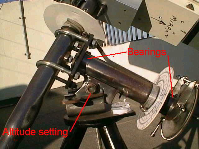
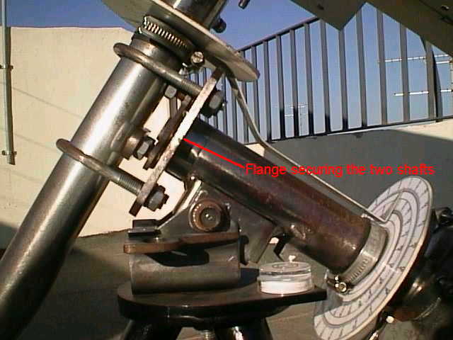
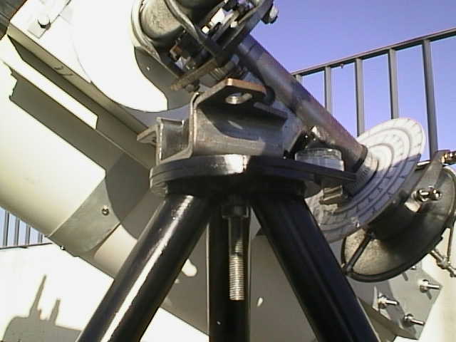
The Fiat shaft ended up as the RA shaft as it had a convenient bracket (which attached the steering column to under the dashboard) which could be used to mount it onto the pedestal. A bolt (also part of the column) secures this and tightening this bolt will set the required altitude setting. A convenient flange on the Fiat shaft would eventually be used to secure the declination shaft to the RA shaft.
The Honda shaft was used as the declination shaft as it was long enough to accommodate the counterweight system.
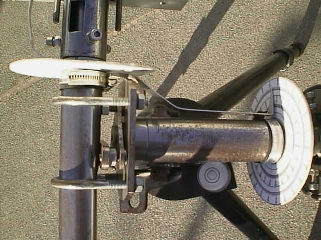
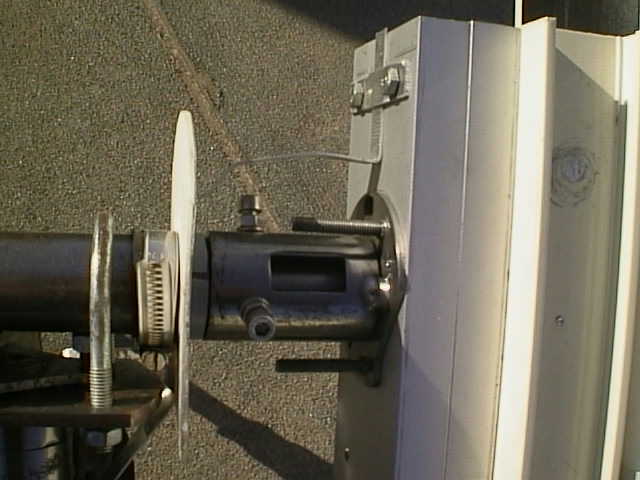
The two shafts were connected with pipe brackets which secured them in an adjustable manner. The extra components needed here was a 6mm iron plate and another small one which could be used to precisely set the two shaft perpendicular to each other.
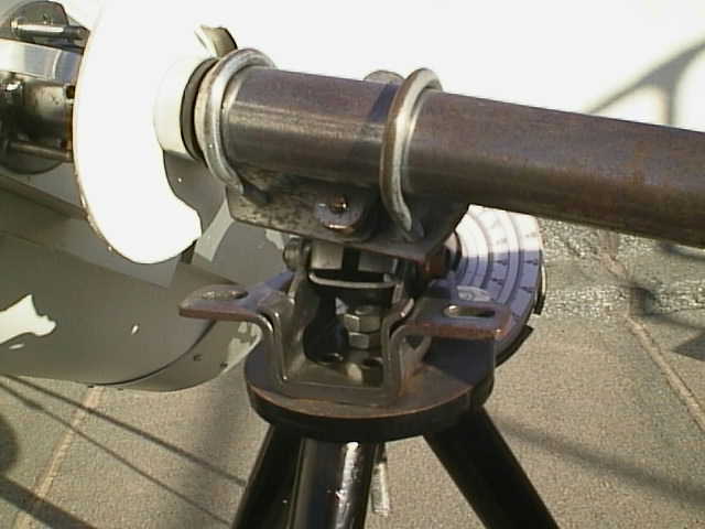
Slow motion control
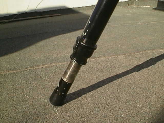
This proved to be more of a challenge and I’m frankly particularly fond of the solution and design. Since the shafts are bearing based, some friction mechanism is required to keep the mount from moving freely. After countless hours pondering about the problem, a solution to this sparked to mind. Finding the suitable worm wheels proved to be nearly impossible (without purchasing them), so I decided to manufacture the wheels. With no milling machines and lathes available, a practical way about this was needed. The solution seemed frail in the beginning but it proved its effectiveness. The ingredients required for each worm wheel are the following:
Method:
1 file the edge of the flange flat all along the circumference
2 file a groove along the flat edge of the flange along the circumference
3 cut a length of stud equal to the circumference of the flange
4 bend the stud to the flange outside circumference (careful not to damage the thread)
5 ‘nail’ the stud to the flange as follows:
make sure the stud’s curvature is such that it stays on the circumference of the flange, seating in the groove made along the circumference as in 2 above
using a 2mm drill bit, drill though the stud and into the flange (sideways) at three equidistant points along the circumference
find suitable 2mm diameter iron ‘rods’ (a steel nail would do). It’s important that these ‘nails’ are tight fit enough that they can be hammered into place not just push fitted.
Use an angle grinder to grind off the excess protruding nail. It doesn’t matter if the thread is grinded as well; as long as this happens along the outside diameter.
6 Voila’ – you have the threaded wheel!
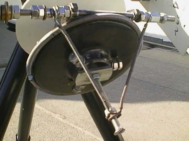
The rest should now become apparent – if we use a straight piece of stud and place it on the flat side of the flange to that there is a length of straight stud in contact with the circular thread along the flange diameter, then turning the straight stud will provide the required slow motion control. The next task is to mount the straight stud on a U shaped bracket (by shaping the flat bar). The U shaped bracket is mounted by three M6 bolts onto the stationery shaft housing and the bracket tips drilled so that the straight stud is seated on the U bracket. Of course, care should be taken to ensure that the correct and exact length is filed off the bracket to ensure proper contact between the straight stud and wheel. This shouldn’t be too much of a problem though. The straight stud was fitted with bushes (8mm outside diameter) which are seated on bracket tips (also drilled to 8mm). The bushes where secured on the stud by ‘nailing’ them to the stud in the same manner as when ‘nailing’ the circular worm wheel on the flange, only this time with a single straight through ‘nail’ and grinded.
A system of high tension springs (made from curtain rail spring) provides the proper contact between the worms and also serves to cater for any inaccuracies in the overall alignment.
The flange was mounted onto the moving shaft by threading three M6 (6mm) bolts onto the inner diameter of the flange and mounting this on the shaft. The three bolts (placed at 120 degree distance) will help centre the flange on the shaft.
A kitchen door knob, drilled at the centre and held by nuts and spring washers will provide the grip required to turn the straight worm stud to provide the slow motion control.
In order to keep the straight stud from moving sideways while turning, a series of nuts and washers keep it in place.
The above arrangement (with a 5 inch diameter flange and 6mm, M6 studs) provide a slow motion control of about one degree of shaft rotation per one rotation of the straight worm driver.
Balancing the scope is essential so that the threads do not ‘slip’ due to the forces exerted on an unbalanced mount. Careful and precise balancing is not difficult to achieve and is a must for proper worm wheel operation without slipping. Do not worry too much if the mount worms ‘slip’ with the tube unmounted.
Slow motion control – remote control
The size of the telescope makes using the slow motion control knobs a bit awkward as the distance between the eyes and an outstretched hand in some cases is smaller than the distance between the eyepiece and the knob! This becomes particularly evident in certain positions of the tube. Again a solution was needed. Belt control was considered but discarded. Ideal solutions centred on the use of flexible shafts, which can be attached to the straight driver worm. Apart from not being available in Malta, these were probably expensive, so more thought was put into this. An incidental visit to the local hardware store yielded the solution – flexible braided water heater pipes. These proved to have adequate axial stiffness due to the braid design. The brass ends of the pipe were threaded to fit the M6 thread on the straight drive worm. A spring washer and nut provided enough friction for the flexible shaft to be ‘remotely’ handled. A useful enhancement was that both ends of the straight worm are available so that the flexible pipe can be mounted in the field to accommodate easy positions. The same kitchen knobs mounted on the ends of the flexible pipes also came in handy.
One obvious disadvantage of the above design is the lack of ‘free wheeling’ movement of the mount. My solution to this was to drive the flexible shafts with a cordless drill which is now part of the ‘astronomy kit’. The cordless drill (keyless chuck) makes an excellent ‘easy’ and fast way of pointing the tube to any position. Final fine tuning can then be achieved by hand turning the flexible shafts. The flexible shafts provide an extension of some 45cms, enough to be reached in any tube position. The 45cms is made up of a 30cms flexible shaft plus an additional 15cms length of stud. An excessively long flexible water heater pipe of 45cms will not be practical to turn.
This flexible shaft arrangement will work even with the pipe bent to an angle of more than 90 degrees.
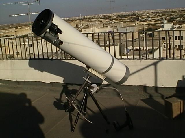
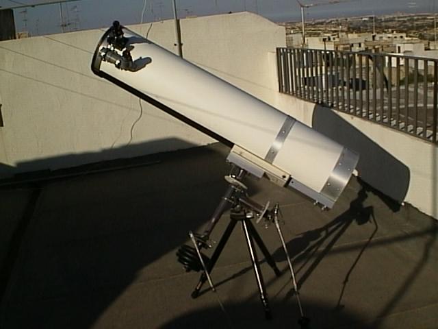
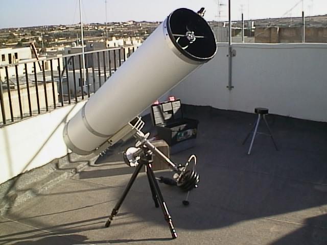
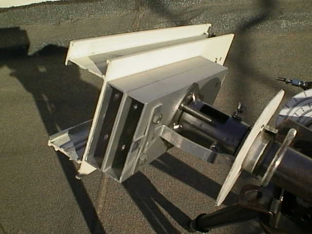
Mounting the tube
The tube was attached to the mount by fitting a 100x50mm aluminium hollow section obtained from a nearby aluminium door manufacturer. Another 100x50mm section slides in this section and is mounted onto the tube itself. A bolt (fitted and removed in the field) secures the two together.
The aluminium section (the mount side) is mounted and fitted onto a flange (part of a steering column) on the declination shaft. The flange is also adjustable so that the tube can be made perpendicular to the declination shaft by means of three M6 bolts.
The pedestal
This first attempt at this was a disaster. It was made by a wooden base fitted with � inch plumbing pipes. However it had loads of ‘wobble’ and utterly unsuitable and was discarded. It was then decided to use my brother’s welding resources to fit a 6mm plate with three 1inch plumbing pipes. The bottom ends of the pipes were fitted with pipe reducers and long threaded � inch pipes which provided the required height adjustment for each ‘leg’. Welding the flat plate on the legs resulted in a slightly curved surface of the plate due to the welding heat, so another plate was afterwards ‘glued’ on the base plate using ‘metal cement’. This provided the required flat surface for the mount to the put on. It also provides the required flat surface for the bubble level to be mounted upon.
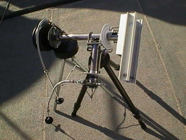
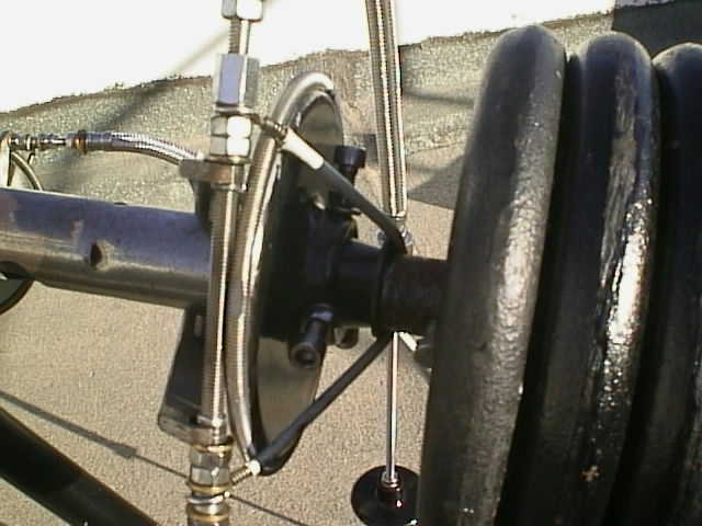
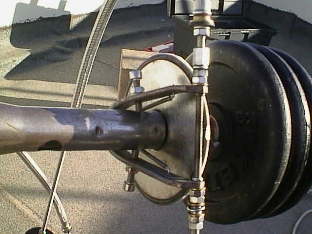
The counterweights
These where obtained from the local gym equipment shop at some US$1.5 per kilo. Some 10kg were needed and these were fitted on the declination shaft. It’s important to fit these without too much axial ‘slack’. At the same time they should be ‘push fit’ onto the shaft. This will help in the overall balancing in any tube position. Putting the counterweights on the shaft in the field requires some care. The declination shaft should be positioned such that is nearly horizontal and supported by something to avoid worm wheel slipping due to the counterweights. The weights should then be inserted and then locked into place. With the shaft still supported the tube should then be mounted.
A note on the mount centre of gravity
It’s important to keep this in mind. The centre of gravity of the mount has to fall within the footprint of the pedestal. It’s also important to keep the shafts as short as possible to avoid flexure and as well to keep the centre of gravity ideally within the top plate of the pedestal.
Aligning the mount
The above design has a number of degrees of movement and each of these need to be accurately aligned so that the overall mount can be usable. The main alignment process involves setting the RA and declination shafts accurately perpendicular to each other. Fix the RA shaft (or declination shaft) exactly vertical by using a spirit level and secure by some form of jig. Attach a long marker (a flat aluminium flat section will do) to the declination shaft and jig up a marker (say, M) at one end of the aluminium marker. Turn the declination shaft 180degrees until the other tip of the aluminium marker reaches M. If the dec and RA shafts are exactly at 90 degrees, then both tips of the aluminium marker will just reach M. If they are not at 90 degrees, they will not. The figure shows an exaggerated non 90 degree angle for ease of demonstration. Adjust the setting of the RA and dec mounting bracket until the 90 degree condition is met. In this way, the perpendicularity requirement is met.
The same procedure should be applied to check the perpendicularity between the declination shaft and the tube aluminium hollow section mount.
Once these two sets of axis are set to 90 degrees, things will get more easier to get the whole mount properly aligned.
Balancing the tube
The tension on the worm wheel should be as minimal as possible to avoid thread ‘slipping’. Balancing the mount and tube assembly is not difficult. First we need to balance the tube. Use a bathroom scales to measure the weight of the tube. Mine weighed some 10kg. We’ll be using this information later. Lie the telescope tube (with an eyepiece and finderscope mounted) on a table. Move the tube to the edge so that an approximate location of the centre of gravity is found. Mark this. Mount the tube on the declination shaft and secure the declination shaft in a horizontal position. Remove the straight drive worm to let the shaft run freely. Adjust the position of the tube on the aluminium hollow section so that when rotated, the tube will stay in any position without help. Once this position is finely found, mark the aluminium sections and drill a hole through both sections. This hole will hold the securing bolt which hold the tube with the declination shaft’s hollow aluminium section. The tube is now balanced. Re-attach the straight worm drive wheel and now check the ‘smoothness’ of the worm. It should be smooth and should not slip with the tube in any position.
The next step is to balance on the RA axis. Remove the straight worm drive on the RA axis. Align the tube parallel to the RA shaft approximately. Mount the counterweight (10kg in my case) on the dec axis and either adjust the weights (I used a combination of 2.5kg, 1.25kg and 0.75kg to get most weight combinations) or adjust the distance of the weights from the centre of the shaft to find a point of balance. Some basic maths on moments can help here. Once the point of balance is found, the mount should turn freely and stay in any position along the RA axis. If the weights used are not the same (eg: 2.5kg + 2.5kg + 2.5kg + 1.75kg), take note of their relative positions. If you change their position, you will lose the balance of the scope. (Again, simple math moment theory will illustrate this). Reattach the straight worm drive and check the smoothness of movement and that the worm will not slip in any position.
The whole assembly should now be balanced, independent of the altitude setting.
The overall weight of the mount and telescope (without the pedestal) should be in the order of 30kg (depending on the weight of the mount). The importance of properly locating the overall mount centre of gravity should now become apparent!
The mount is now complete. I have neatly scraped and brushed the ironworks and spray lacquered everything to get a nice shiny finish. As for the various bolts, I’ve used M6 stainless steel bolts with hex heads. I’ve used a 5mm drill bit and a 6mm taps set to thread in the various iron shafts and bits. (These bolts were possibly the most expensive part of the mount!!).
The tube
The first step for this is to find the exact focal length of the primary mirror. Finding this is clearly indicated in John Dobson’s manual. Mine turned out to be some 20mm different from the theoretical one. Getting the exact focal length (accurate to the nearest mm) is important for proper location of the focusser on the tube. If the focal length is f, then the ‘stop’ (the top edge) of the focusser (set at mid travel and without an eyepiece fitted) should be f away from the primary (considering the light path gets a 90 degree turn by the secondary flat). Clearly, the depth of the mirror cell, the thickness of the mirror and the diameter of the tube will all have to be taken into account for an exact determination of the focusser hole. Again, Dobson’s ATM construction manual explain better the calculations.
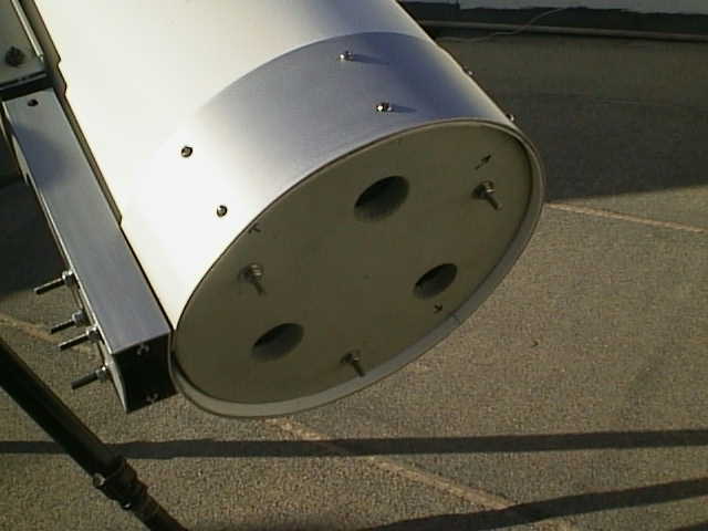
Sonotubes (widely mentioned in US ATM manuals) are not available in Malta. I decided to use 1mm thick PVC sheets, available from advertising display manufacturers. They quite cheap and a tube made up of two sheets (for a thickness of 2mm and to provide the bending radius) provides enough rigidity. The sheets were not glued together; just placed on each other. The mirror was 250mm, it’s important to leave a clearance of at least 1inch around the mirror. The tube diameter was therefore 300mm. Three rings (width around 50mm) where made from aluminium strips (2mm thickness) and bent to a 150mm radius. Holes for self tapping screws where drilled after the strips were bent, otherwise you’ll have problems when bending the aluminium strips. Each ring was then finished with a small aluminium plate to retain the annular shape.
Two of the rings are screwed to the 100 x 50mm aluminium hollow section. The hollow section will serve to mount the tube onto the equatorial mount.
Two PVC sheets are then cut so that an overlap of around 50mm would be in place when the sheets are rolled into a 300mm tube. Before rolling the PVC sheets, I used a self adhesive black velvet sheet on the (future) inside of the tube. This will provide as anti reflective coating on the inside of the tube.
Once the sheets are rolled, they are inserted into the rings mounted on the aluminium section; the other ring is dressed (but not screwed) on the other end of the PVC tube for rigidity.
At this point, careful manipulation of the PVC sheets should result in a very good cylindrical shape. Once this is set, I used a hot awl to pierce the PVC through the holes in the lower two aluminium rings. After each hole, a self tapping screw is screwed in place and a self tapping screw retaining clip used to secure the screw in place rigidly.
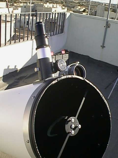
The third aluminium ring is then screwed in place. The exact location of this third ring should be carefully calculated as it will also serve to support the spider. Prior to fixing the ring onto the tube, holes for the spider vane screws should be marked and drilled. Again, I would refer you to the numerous methods of calculating the exact lengths and location of the spider with respect to the other optical components.
The Mirror Cell
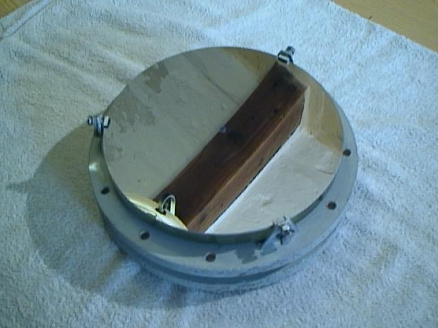
This will hold the mirror in place and also facilitate collimation and to a certain extent will also yield some millimetric comfort in case of slight errors in optical lengths calculations. Again, there are various sites which detail construction of the mirror cell. I used two chipboard, 3/4 inch thick boards to make the cell. These boards were cut circular to fit exactly the inside of the tube. It should not be tight fit since the inner plate will be slid in the tube for collimation. they were both painted with two coats of primer to seal the chipboard. The top board was fitted with three M6 bolts which where fixed to it. The bottom board was drilled with three holes so that the fixed bolts will run through them . Springs (also from the steering columns!!) were dressed on the bolts and between the boards and three nuts and washers on the bottom board secured the whole assembly. The nuts provide the required collimation and distance adjustment.
The top board was fitted with aluminium L plates (three of them) to hold the mirror using small pieces of rubber and bolts. A 'vibration' test was made on a sofa with the mirror cell assembly (including mirror) to check stability and to see whether the mirror is secure.
The bottom and top boards where drilled with wide holes for air circulation. The whole assembly was then inserted in the lower part of the tube and screwed to the edge of the lower aluminium ring.
 |
The mirror cell viewed obliquely from the mirror side. The mirror is held in place with three aluminium L plates. Note the 'small' ventilation holes around the perimeter of the upper board. Enlarging the image, one can also see the tiny black adhesive velvet dot placed at the centre of the mirror. |
 |
Another view of the mirror cell, this time from vertically top of it. Accuracy in the cutting of the boards, the centering of the mirror and the placing of the mirror aluminium holders will make aligning and collimation easier, apart from an aesthetically pleasing arrangement. |
 |
A side view of the mirror cell. Small pieces of rubber provide friction to keep the mirror in place and also avoid damage to the mirror. The bottom bolf on the L plate keep the mirror in place in a horizontal plane. The top bolt keeps a yet smaller aluminium L plate in place, securing the mirror in the vertical place. Small pieces of rubber in this small L plate prevents any damage to the mirror. The flexibility of the aluminium plates act as vibration absorption preventing further damage to the mirror. This plate arrangement was required as there were no holding indents in the mirror sides. Smll rubber pads glued to the top board seats the mirror on the baord to prevent direct contact of mirror with board, although this is not necessary. |
 |
Another side view of the mirror, this time showing the springs on the collimation bolts. At each end of the spring, a large washer acts as a stopper to the springs, rather than have the mirrors in contact directly with the boards. |
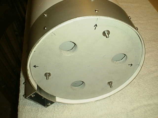 |
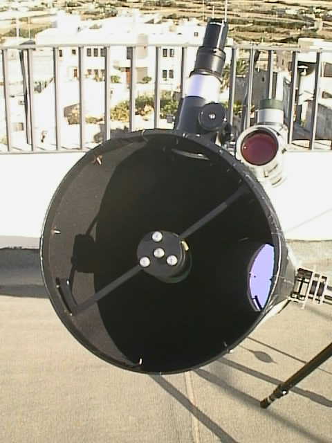
A view of the assembles mirror cell in the tube. The cell is held in place with self tapping screws by the edge. Note the large three holes used for ventilation purposes. These holes and the other small holes on the other board ensure free movement of air within the tube to facilitate stability of air in the telescope. The three nuts visible here can be adjusted to provide proper collimation. Wingnuts would probably do a better job, though. |
Marking the centre of the primary mirror.
Before mounting the mirror cell on the tube, the mirror needs to be marked exactly on its centre to serve for collimation purposes. The mirror was place with it's face flat on a piece of thin paper. The circumference is then marked on the paper. The mirror is then removed and the paper cut along the marked circumference. The paper is then folded in four; this needs to be done as exactly as possible. The resulting quarter circle is then nipped at the centre with a straight cut to present a small square hole (6 mm) in the middle of the paper. I then used a stationary puncture on a small piece of black adhesive velvet (used to line the inside of the telescope) and fixed this on the mirror where the hole in the paper gets to after aligning the paper exactly on the mirror. This small 'dot' will not affect the optics as it falls well within the secondary mirror shadow on the primary anyway.
Fitting the focusser
Once the exact location of the spider and secondary mirror is found, the focusser can be mounted. A circle the size of the focusser inner tube is marked on the side of the tube. I have chosen to mount the focussed at 90 degrees from the tube mount so that with the tube pointing at the celestial pole, the focusser would be on the side of the tube. The focusser can then be mounted with four self tapping screws with retaining clips. The PVC provides enough rigidity to give a good seating for the focusser. Somehow, I managed to err by some 5cms in the location of the focusser, so I had to recut another hole in the tube. Although a cosmetic aberration, this was remedied without a lot of hassle.
Collimation
Again I used the method in Dobson's manual, so there's no need to repeat what's already excellently explained elsewhere.
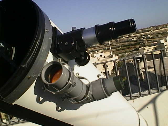
Finberscope construction
Finderscope Optics
I really thought I could do away with this. Having never peeped through a telescope I could not appreciate how difficult it is for a novice to target celestial objects. One try through the scope convinced me that I do need the finderscope, so off I was to my next 'mini-project'. Of course I couldn't buy a ready finderscope (vide above criteria) so I thought about how to go about this.
The optics had to be bought though so off to a visit to the local 'flea market' where I got my hands on a low cost binoculars (around US$30). It was a 7 x 50 binocular set with lousy plastic case moulding but with glass (!) optics which seemed to do the job. A bonus was a crosshair on one of the eyepieces. In a couple of hours the binoculars was disassembled to reveal the objective lens, the eyepiece with crosshair and prisms. I decided to go for a right angle view finderscope so I needed the prism.
Findescope Housing
I opted for a PVC drain pipes and fittings to construct the housing. I used the following:
- 50mm straight adapter
- 50mm 90degree elbow
- 50mm PVC pipe
- 50mm to 32mm reducer
The 50mm straight adapter would hold the objective lens. The inner side of the adapter was lined with the same adhesive black velvet for antireflection. A short piece of 50mm pipe connects the adapter to the 90degree elbow; the elbow will contain the prism. The eyepiece will fit inside the 32mm side of the reducer which in turn fits inside the 90degree elbow. Sanding the reducer ensures that the eyepiece can be moved for focussing and a threaded M6 bolt will hold the focus.
The prism was mounted inside the 90degree elbow after cutting flat the corner and fitting it with the prism mounted on a 2mm thick PVC sheet. The prism was fitted between two small bolts through the PVC sheet and held in place with silicone. The inner side of the elbow was also lined with the self adhesive velvet.
The eyepiece was fitted inside the 32mm side of the reducer and a short piece of 40mm pipe covered the whole eyepiece assembly and the rubber eye 'holder' from the original binoculars was glued to this 40mm pipe for added 'comfort'.
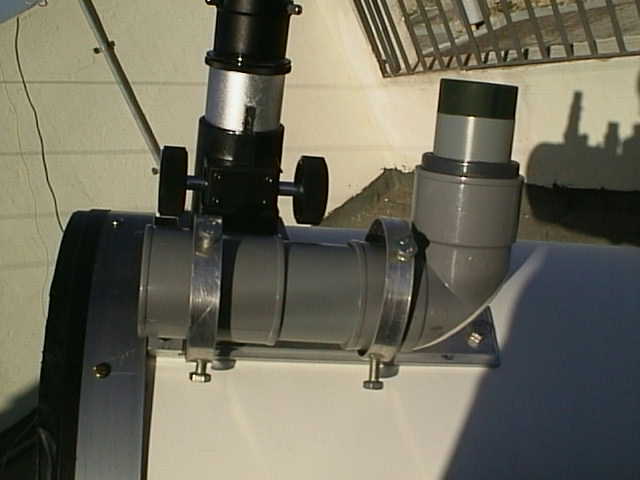
Finderscope mounting and adjusting rings
An aluminium strip was mounted on the tube adjacent to the focusser. Another aluminium strip (3mm thick) was fitted with two aluminium rings (made from 1.5mm aluminium strips) at each end. The aluminium rings have a diameter of around 80mm providing enough clearance for finderscope alignment. Each ring has three adjusting bolts which hold the finderscope and enables proper alignment. The finderscope assembly connects to the tube aluminium strip by two very short bolts so that the finderscope can be easily removed and alignment kept.
Again, aligning the findersope is a standard procedure which can be found in numerous places on the net but basically it involves pointing the scope on a far land based target and adjusting the finderscope mount so that both view centres coincide as exactly as possible. To increase precision, higher magnification eyepieces should be progressively used.
Adding alignment crosshairs
The eyepiece fitted had standard crosshairs in built which proved useful. At the present time, I'm using a particular type of polar alignment which involved pointing the scope to the Polaris, off-centering it to point to the true celestial north and rotating the tube (RA wise) so that the Polaris follows a concentric path on the crosshairs. The trouble with this is to find the true celestial north initially. I decided to construct a crosshair with alignment radial lines along the Polaris and the 24 Ursae Minoris - Delta Ursae Minoris pair.
The first figure below shows the view of the Polaris region through a 7 x 50 finderscope (mirrored to reflect the view through the finderscope). The centre is the exact celestial north. The star close to the centre is the Polaris and the pair of stars in the lower right quadrant is the 24 Ursae Minoris - Delta Ursae Minoris pair. The second figure shows the fabricated crosshair with the two radial lines along these stars. This template crosshair can be used to accurately align the telescope to the true north.
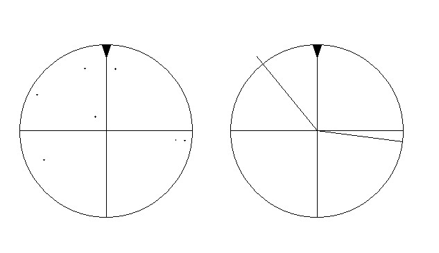
The second figure was laser printed on a clear transparency, cut and fitted onto the existing crosshair glass in the eyepiece. The transparency was fitted using a PVC 32mm sleeve so that this sleeve pushes the transparency against the glass crosshair. True that the transparency introduces optical imperfections as well as putting in focus the imperfections on the transparency, but it does serve the purpose and is a simple yet effective way to make an 'alignment' crosshair.
Tools required
I do not posses the more sophisticated lathes and milling machined (though I wish I had to space to own these). All the above was constructed with the following tools. The only 'subcontracted' work was the welding resources made available by my brother.
- hand saw
- files
- M6 tapping set (US$6)
- electrical drill and drill bits (5mm, 6mm, 2mm)
- emery cloth
- 'Stanley' knife
- awl
- screwdriver set
- jigsaw cutter
- vernier scale
- vice
- pliers and cutter
- angle grinder (this helps!)
- centre punch
- drill stand
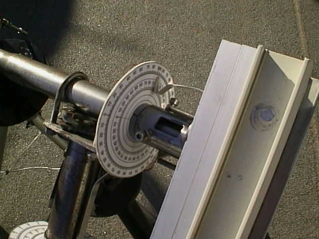
Setting Circles
Initially I thought these would not be required, however being new to the subject I needed some assistance in targeting celestial objects and thought I would give these a go. An excellent site which contain images of setting circles which can be used is at *** put in sitename here. The setting circles consist of two calibrated circles, the declination and RA circles which help you to point to specific objects. Many sites I've visited do not recommend the use of setting circles and consider them as useless and inaccurate, however, when properly polar aligned, I found mine to be extremely helpful, particularly the declination one. The setting circles were first laser printed and then laminated both sides. They were then cut and mounted on 2mm thick PVC sheets and inserted in the respective declination and RA shafts. They were held in place by means of jubilee clips with a rubber gasket to firmly hold the circles in place, yet these can be rotated.
Setting the 90degree declination is crucial for accurate setting circle use. This was done by the initial polar alignment of the mount and tightening the jubilee clip to fix the circle in place. Once fixed, there is no need to touch the declination circle again in future use. The pointers were made by attaching a pointed aluminium strip to a suitable place on the mount and fixing a transparency marker at the tip of the strip.
Software to use
Of the various software available on the net as demo or otherwise, I found the starrynight backyard by space.com (www.space.com) as the most user friendly, informative and interactive to use. It can be downloaded as a full demo and purchased at a decent price if required. There are other numerous utilities ranging from telescope optics simulation to telescope dimension calculation programs.