JUNE 20, 2009
| BUILDING A RIDER CAR JUNE 20, 2009 |
|||||||||||||||
| [home] | |||||||||||||||
|
|||||||||||||||
|
|||||||||||||||
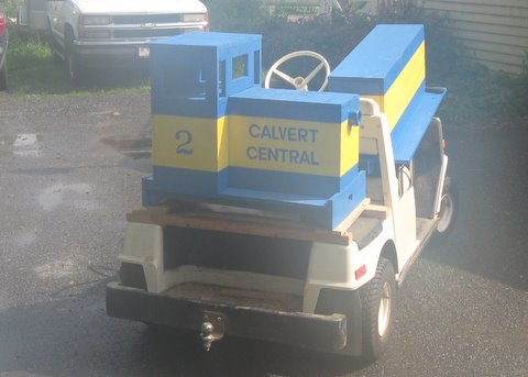
| THE WHOLE TRAIN ON A GOLF CART - Yep, they both fit just fine. There was a storm brewing, so I couldn't wait for the camera lens to warm up. By the time I got to the railroad, I barely had time to unload and take pictures before the rain. | |||||||||||||||
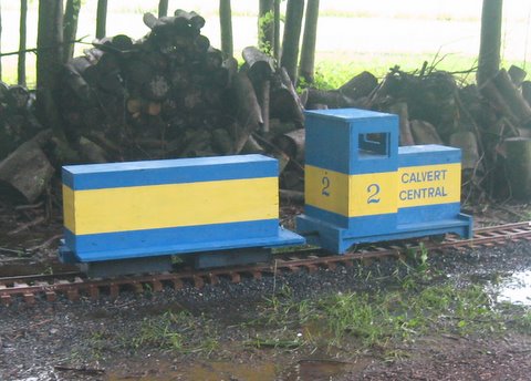
| COUPLED UP - The newly completed rider car is ready to go. On the previous page you can see pictures of the test run for the car's suspension system. | |||||||||||||||
|
|||||||||||||||
|
|||||||||||||||
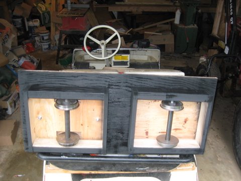
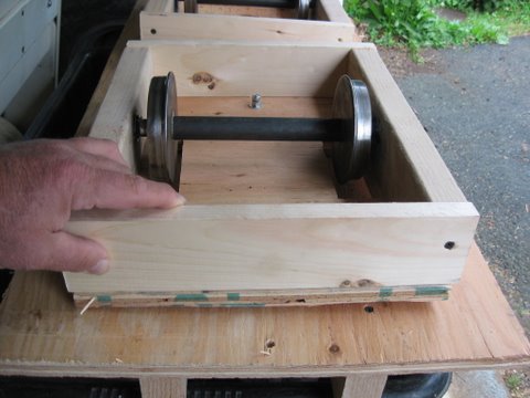
| ANOTHER VIEW UNDERNEATH - On the left axle assembly you can see the bolts which enable the pivot action, and open areas for the wheels. | |||||||||||||||
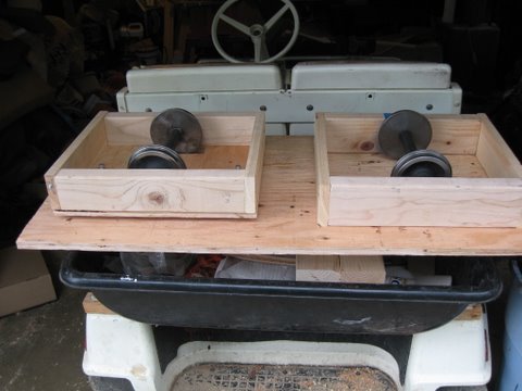
| UNDERCARRIAGE - Under the deck is a pair of single wheelsets, the left one able to pivot side to side in order to track better. The axle ends ride on ball bearings. | |||||||||||||||
|
|
||||||||||||||
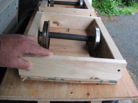
| PIVOT - These two pictures show the pivoting action of the front axle. The assembly is basically a 13 by 15 inch box with a plywood bottom with cutouts for the wheels. Ball bearings are mounted in 1 1/8 inch holes in the 2x4's. The car is 18 by 40 inches, and the axles are 20 inches apart. (The Critter's wheelbase is 22 1/4 inches.) | |||||||||||||||
|
|||||||||||||||
|
|||||||||||||||
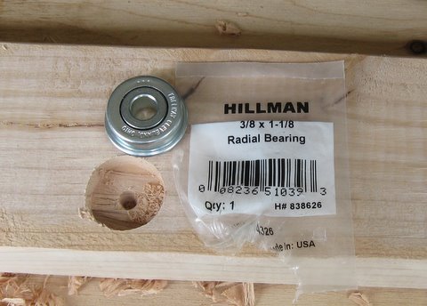
| INSTALLING A BEARING - I found bearing assemblies at Tractor Supply. I drilled a 1 1/8 inch hole, inserted the bearing, and secured it with screws alongside. | |||||||||||||||
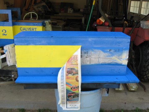
| MY FAVORITE PART OF PAINTING - Removing the masking and seeing the finished product. I wish the spray paint would cover better, but it worked out OK. | |||||||||||||||