4.1.Graduação
4.2.Mestrado
4.3.Especialização
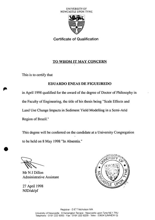
4.4.Doutorado
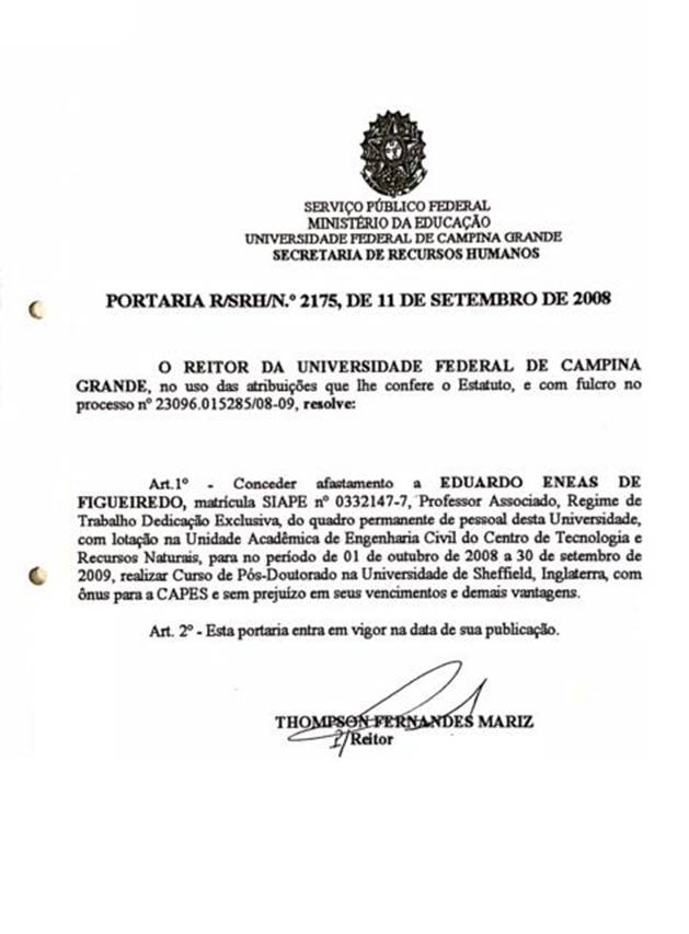
4.5.Pós-Doutorado
PLANO DE ESTÁGIO PÓS-DOUTORAL
DADOS DO PROJETO
TÍTULO:
MOSESS 2D – UM MODELO BIDIMENSIONAL DISTRIBUÍDO PARA SIMULAÇÃO DO ESCOAMENTO E EROSÃO DO SOLO EM ESCALA DE BACIA
PROPONENTE:
Prof. EDUARDO ENEAS DE FIGUEIREDO ([email protected])
Universidade Federal de Campina Grande – UFCG
Centro de Tecnologia e Recursos Naturais - CTRN
Unidade Acadêmica de Engenharia Civil - UAEC
Área de Engenharia de Recursos Hídricos – AERH (Cx Postal, 505); F: 83 33101156
58100-970 - Campina Grande, PB
INSTITUIÇÃO ONDE SE REALIZARÁ O PROJETO:
The University of Sheffield (http://www.sheff.ac.uk)
Department of Geography
Winter Street
SHEFFIELD
S10 2TN
Telephone: 0114 222 7905
Fax: 0114 222 3601
SUPERVISORES DO PROJETO:
Professor ANTHONY J. PARSONS
Telephone: 0114 222 7952
Fax: 01144 279 7912
Email: [email protected]
Professor JOHN WAINWRIGHT
Telephone: 0114 222 7951
Email: [email protected]
PERÍODO DO PROJETO:
Início: Outubro/2008
Término: Setembro/2009
DATA PROGRAMADA PARA A VIAGEM:
Segunda quinzena de Setembro de 2008
SUMÁRIO
RESUMO
1-INTRODUÇÃO E OBJETIVOS
2-REVISÃO DO ASSUNTO
3-JUSTIFICATIVAS
3.1-Limitações na Utilização de Modelos Importados
3.2-Reciclagem e Atualização do Proponente
3.3-Instituição Escolhida/Supervisão
4-PROPOSTA DO MODELO - METODOLOGIAS
4.1-Componente de Fluxo do Modelo
4.1.1- Precipitação
4.1.2-Intercepção vegetal
4.1.3-Evapotranspiração potecial (Ep)
4.1.4-Evapotranspiração real (Ea)
4.1.5-Tensão do solo
4.1.6-Umidade volumétrica
4.1.7-Umidade de saturação do solo
4.1.8-Condutividade hidráulica
4.1.9-Capacidade de infiltração
4.1.10-Lâmina do Escoamento superficial (q)
4.1.11-Escoamento Sub-superficial
4.1.12-Escoamento Subterrâneo
4.1.13-Propagação do escoamento
4.2-Componente de Erosão do Modelo
4.2.1-Erosão pelo impacto da gota de chuva
4.2.2-Erosão pelo fluxo
4.2.3-Capacidade de transporte do fluxo
4.2.4-Deposição de Sedimentos
4.3-Estrutura de Cálculo do Modelo
5-TESTE DO MODELO
5.1-Região de Estudo
6-PLANO DE TRABALHO
7-CRONOGRAMA
8-REFERÊNCIAS BIBLIOGRÁFICAS
ANEXOS
Carta do Chefe do Departamento de Geografia da Universidade de Sheffield/UK
Carta do Professor Anthony Parsons
Currículum Vitae do Proponente
MOSESS_2D
A model for runoff and soil erosion
prediction at the catchment
scale
MOSEE
Um modelo para simulação do Escoamento
e Erosão do solo em bacias
hidrográficas
D O C U M E N T A T I O N
Author: E. E. de Figueiredo
UAEC/UFCG/CTRN
Brazil
Post-doctoral project carried out in the
University of Sheffield/England/UK
Support: CAPES/BRASIL
Oct 2008-Sept 2009
CONTENTS
1-INTRODUCTION 1
2-BRIEF DESCRIPTION OF THE MODEL 3
3-MODEL’S COMPONENTS AND PROCESSES 5
4-THE FLOW COMPONENT 6
4.1-Rainfall and Interception 6
4.1.1-Rainfall 6
4.1.2-Interception 6
4.2-Evapotranspiration 7
4.2.1-The equation of Blaney-Criddle (1950) 8
4.2.2-The method based on net radiation 8
4.2.3-The method based on aerodynamic characteristics 9
4.2.4-The method of Penman 10
4.3-Infiltration 10
4.4-Percolation 11
4.5-Soil Matrix Potential 12
4.5.1-Soil Tension 12
4.5.2-Non-Saturated Hydraulic conductivity 13
4.5.2.1-The method of Brooks & Corey (1964) 13
4.5.2.2-The method of Campbel (1974) 14
4.5.2.3-The method of Saxton et al (1986) 14
4.5.2.4-The method of Van Genuchten (1980) 14
4.5.3-Saturated Hydraulic conductivity 15
4.5.3.1-The method of Saxton et al (1986) 15
4.5.3.2-The method of Rawls et al (1998) 15
4.5.3.3-The method of Brakensiek et al (1998) 16
4.5.3.4-The method of Cosby et al (1984) 16
4.5.4-Moisture Content of the Soils 16
4.5.4.1-Moisture content between rainfall events 16
4.5.4.2-Moisture content during rainfall events 19
4.6-Interflow 19
4.7-Surface Flow 20
4.8-Overland Flow 22
4.9-Runoff Routing 22
4.9.1-The Muskingum Procedure 22
4.9.2-The SCS Convex Procedure for runoff routing 24
4.9.3-Time of Concentration 24
4.9.3.1-The method of Kirpich (1940) 24
4.9.3.2-The method of Kerby (1959) 24
5-SEDIMENT COMPONENT 25
5.1-Erosion by rainfall 25
5.2-Erosion by runoff 27
5.3-Total Load of Sediment Available for Transport 28
5.4-The Sediment Transport Capacity by the Flow
5.4.1-The Equation of Yalin (1963) 28
5.4.2-The Equation of Engelund-Hansen (1967) 29
5.4.3-The Equation of Laursen (1958) 29
5.5-Sediment Transport and Deposition 31
5.5.1- Conditions for Transport and Deposition 31
6.MODEL’S WORKABILITY 32
6.1-Description of the Study Area 32
6.2-Parameterization of the Model 38
6.2.1-Micro-basin M3 Parameters 38
6.2.2-Representative Basin of Sume Parameters 40
6.2.2.1-Gangorra parameters 41
6.2.2.2-Jatoba parameters 42
6.2.2.3-Umburana parameters 43
6.3-Simulation Results 44
6.3.1-Micro-basin simulations 44
6.3.2-RBS Simulations 49
BIBLIOGRAPHIC REFERENCES 57
APENDIX A: VARIABLES AND CONSTANTS 61
APENDIX B: CHARACTERISTICS OF THE COMPUTATIONAL CODE 67
1-INTRODUCTION
A soil erosion model is generally interfaced with, and driven by, a hydrological model. For soil erosion, rainfall and runoff are the dominant agents of detachment and transport, while overland flow plays an important role in soil transport and deposition (Vanoni, 1975). It is therefore important to take into account the interactions between the rainfall and catchment characteristics for an adequate runoff-erosion modelling (Storm and Refsgaard, 1996).
Runoff generation is principally governed by the rainfall characteristics such as duration, intensity and spatial distribution, and by the dynamics of the infiltration process which depends on initial conditions of soil wetness, soil structure and its properties, vegetation cover and topographic features. The rainfall intensity defines the rate of incoming water. It can infiltrate in the soil depending basically on the soil infiltration capacity (Hillel, 1971).
Basically two types of runoff generation can occur: the infiltration excess overland flow described by Horton (1933), and the soil moisture excess over saturation. The first mechanism can be described by comparing the rainfall rate i with the infiltration capacity f. If i < f, all water infiltrates at the rate defined by i. Otherwise, when i > f, it infiltrates at the rate defined by the infiltration capacity f, the soil surface becomes saturated, and the excess of water will pond. The second mechanism is soil filling owing to a long-duration rainfall or elevation of the water table, after which the incidence of rainfall will produce overland flow (Dunne, 1978). Infiltration excess overland flow commonly develops in arid and semiarid zones, in shallow soils of low infiltration capacity, in impervious areas, and in regions with low precipitation but with high intensities, such as semi-arid regions. In such regions, subsurface flow and baseflow play a minor role and contribute to a lesser extent to the total flow from occasional alluvium located along the river bed (see IAHS, 1979).
Soil erosion is a consequence of the processes described above. It incorporates the processes of detachment, transportation and deposition of soil particles governed by erosive agents such as precipitation, runoff, wind and gravity (Vanoni, 1975). The gross amount of soil detached by these agents is the soil erosion. The net amount of soil moved off a particular field or area is the soil loss, which is the difference between the gross amount of soil erosion and deposition. The sediment yield at a particular point that drains a certain area is the soil loss delivered to that point of reference. Generally the soil loss is expressed in units of weight per unit area (e.g., kg/ha, t/km2) while sediment yield is commonly expressed in units of weight per unit area per unit time (e.g., t/km2/year). However, the soil erosion process may be related to its travel distance (Wainwright et al., 2008; Parsons et al., 2004; 2006) instead of dividing the load of sediment (gross or net) by the basin area. It is important to point out that runoff is the main sediment-transporting agent and therefore soil erosion and transport can conveniently be expressed in terms of sediment discharge (e.g., m3/s, t/s, kg/s). In such way, the use of equations of sediment transport capacity is plausible.
The brief review above is central to develop a rainfall-runoff-erosion model, which can be as simple as a function between discharge versus precipitation and catchment characteristics, or may follow a more complex algorithm according to physical principles. Basically, a mathematical model is designed to simulate the catchment responses such as runoff and sediment yield.
This document presents the model MOSESS_2D to simulate runoff and soil erosion processes at the catchment scale, developed during the post-doctoral project conducted at the Department of Geography in the University of Sheffield/UK from Oct 2008 – Sept 2009 with the support of CAPES/BRAZIL.
The model was developed following the runoff generation mechanisms described previously. The assumptions for its development are simple and make it mathematically simple. The model workability is demonstrated right through some applications of the model to some catchments in the semi-arid region of Northeast Brazil.
A description of the methodologies in the model is given herein. Variables and constants seen in the text, as well as the main characteristics of the computational code are described afterwards in the appendices A and B respectively.