The new swing arms would be attached to the hull in a different manner allowing for a small bit of extra room inside. A person would think that a 1/6 scale tank model would have plenty of room but when faced with batteries, motors and other items needed to be installed, the extra room quickly evaporates.
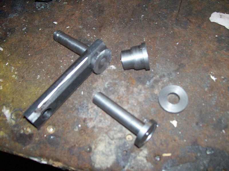
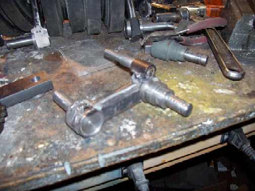
The new swing arms were constructed in metal by using flat stock with 13/16 hex bolts. I also used some round stock I had on hand for the stepped spacer and shock arm. The complete arm have 6 individual pieces, 3 shafts, 1 stepped spacer, 1 additonal spacer and the body of the arm. The assembly would be welded together and a final application of body filler to fill in the gaps.
The shafts used were turned from a grade 5 hex bolts. I chose to use this, as the material was readily available from any hardware store. The first operation was to turn the hex portion of the bolt down to the proper diameter on the lathe. Once done, I turned the bolt around and begin turning the shaft to the proper diameter. These were cut to length with a groove applied for a C-Clip on the wheel shafts The stepped spacer was turned on the lathe, bored and then parted in one operation. The shock arm shafts were also done on the lathe.
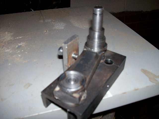
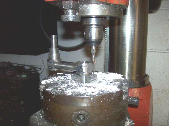
Each piece was cut a little longer than needed. The holes were bored to proper size on the mill to insure the holes were spaced properly.
Once this operation was complete, I milled beveled edges onto top and bottom of the swing arms to gain the rounded apearance.
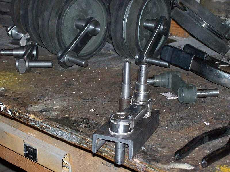
Only 4 swing arms per side need the shock arm as the front swing arms had no slot on the full size tank.
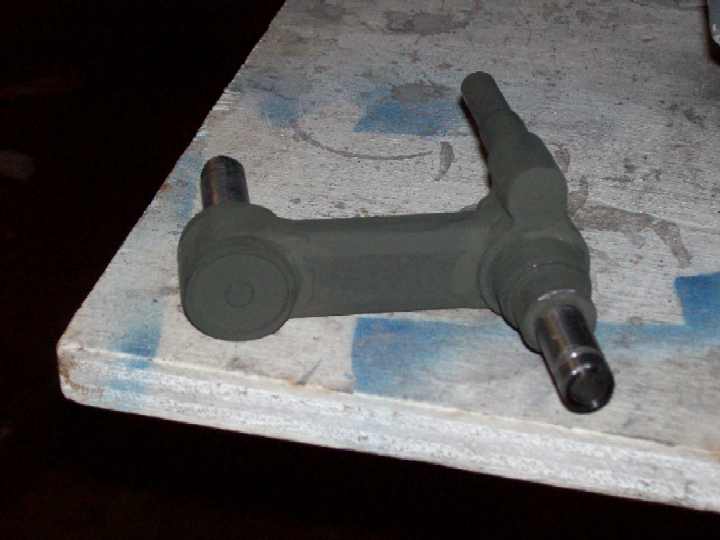
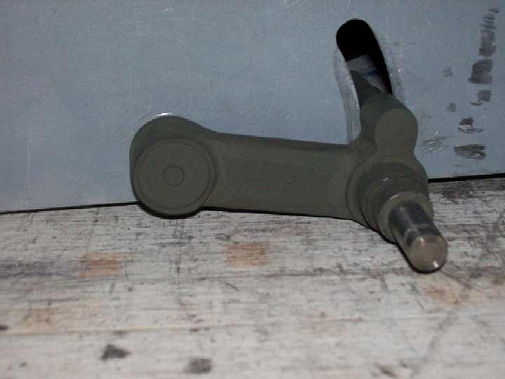
Sharp eyes may notice a few details not added to the swing arm at this point. These details such as the end cap for the swing arm and the raised welded part on the top of the swing arm for the rubber stop pad mounted on the hull have planned but not included at this point.