| Repairing Carl Zeiss Abbe Refractometer |
| By Dushan Grujich, on April 15th. 2013 |
|
|
|
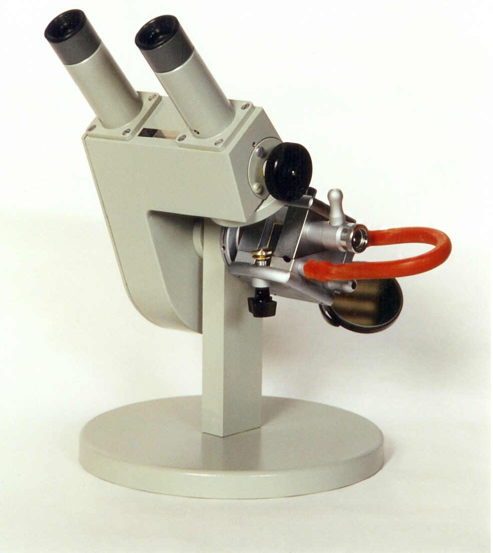
| Carl Zeiss Abbe Refractometer Type G |
| Ernst Abbe designed refractometer in 1869, the original design was so successful that even today, 143 years later, the same principle is still used in new devices. The unit shown above, made in Zeiss factory in Jena is later version which has measuring prisms placed in an enclosure through which heated water, controlled by thermostat, can circulate and keep both, the measuring prism and sample at preset temperature, usually 20º C, thus ensuring that the readings are always correctly taken at the same temperature. |
|
|
|
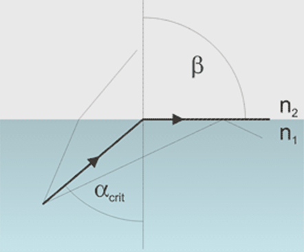
Critical angle |
|
Critical angle is the incident angle at which light - instead of getting to the other side of phase boundary - gets refracted in such a way that it becomes parallel to the phase boundary surface. For smaller incident angles rays get through the boundary, for larger they get reflected back. |
|
|
|
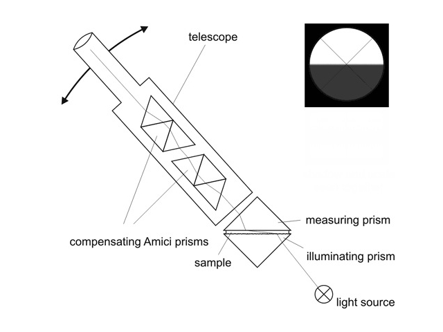
Diagram showing principle of Abbe refractometer |
|
The
working
principle of Abbe
refractometer is based on critical angle. Sample is placed between two prisms -
measuring and illuminating. Light enters sample from the illuminating prism,
gets refracted at critical angle at the bottom surface of measuring prism, and
then the telescope is used to measure position of the border between bright
and light areas. Telescope reverts the image, so the dark area is at the
bottom, even if we expect it to be in the upper part of the field of view.
Knowing the angle and refractive index of the measuring prism it is not
difficult to calculate refractive index of the sample. Surface of the
illuminating prism is matted, so light enters the sample at all
possible angles, including those almost parallel to the surface.
|
|
To
prevent dispersion
Abbe
added two compensating Amici prisms into his design.
Not only can telescope position be changed to measure the angle, also the position
of Amici prisms can be adjusted, to correct the dispersion. In effect edge of
the shadow is well defined and easy to locate. |
|
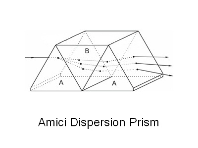
| The Amici dispersion prisms generate dispersion of polychromatic light with simultaneous correction of divergence. All the dispersed beam output from the prism are parallel to the input beam. These prisms consist of three prisms, which are cemented together. Two of the three prisms (both A prisms, shown in the drawing) are made of different material than the other prism (B prism). Typical combination of materials is Flint glass for A and Crown glass for B. |
|
|
|
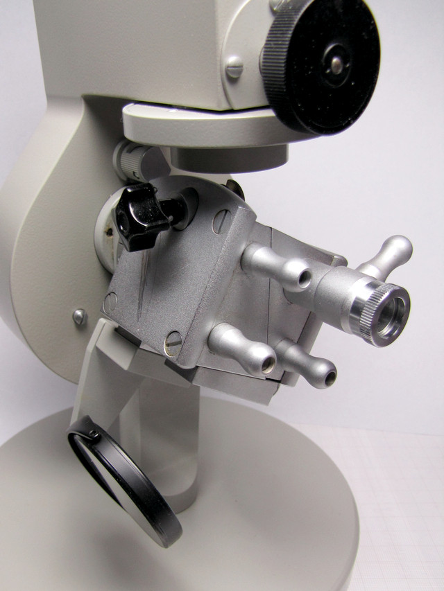
The main parts and controls of the Abbe Refractometer are: |
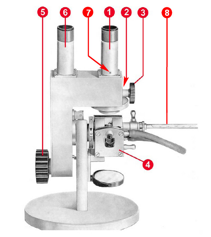
| 1 | Focusing telescope, | ||
| 2 | Colour compensator with graduated circle, | ||
| 3 | Setting knob for colour compensator | ||
| 4 | Standard prism body, water heated | ||
| 5 | Setting knob for prism and graduated circle turn | ||
| 6 | Reading microscope | ||
| 7 | Calibration screw - special wrench needed | ||
| 8 | Control thermometer |
|
Refractometer has come in non functional state, although nothing was broken. Careful examination has shown that the two Amici compensating prisms, located in the right hand side focusing telescope, were loose and have moved disabling the use of compensating mechanism. The cause of the prisms getting loose is deterioration and disintegration of cork used for mounting prisms in their places. | ||||||||||||
|
| ||||||||||||
|
| ||||||||||||
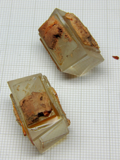
| Amici prisms shown with the cork mountings, or rather what is left of it. | ||||||||||||
| ||||||||||||
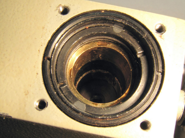
| Image of part of the refractometer with the focusing telescope removed shows the two tubes in which the two Amici prisms were mounted. Before cleaning, particles of cork are still visible. | ||||||||||||
| ||||||||||||
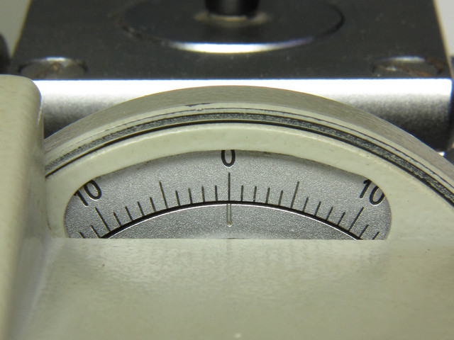
| Compensator scale shown close up | ||||||||||||
| ||||||||||||
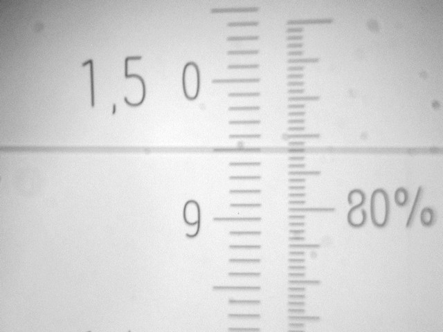
| A peek through the measuring telescope shows both scales, Refractive Index and Brix concentration in % | ||||||||||||

| ||||||||||||
| A view through the focusing telescope with no compensation, both Amici prisms removed thus the rainbow colour along the boundary line. | ||||||||||||
| ||||||||||||
| Here the Amici prisms cleaned from the remnants of the rotted cork. | ||||||||||||
| Not knowing the cement used originally to mount cork sections to prisms and afraid of doing damage to the cement used to join prisms to each other, I had no choice but to apply the only cleaning method which cannot in any way act on cement. Thus I resorted to the purely mechanical cleaning method of carefully scrubbing off all the remains of rotted cork and glue binding it to the tiny glass plates used to strengthen the prism assembly. A tad bit slow and touchy work, but it had to be done in the most non-destructive way possible. | ||||||||||||
|
The next step was to choose the cork and use it for making the sections for mounting prisms back into their tubes. The two Amici prisms are identical, thus it matters not which one goes above and which one goes below. Their positioning seems not to be critical regarding their exact position along the optical path. There also seems to be some liberty in radial positioning of prisms as long as they are placed parallel with the optical path and are as close as possible to its centre. Decision to use cork was based on the fact that it is traditional way of mounting prisms, as well as the simplicity of using it. | ||||||||||||
|
Thus I started mounting prisms with cork, and that is where I hit a brick wall, head on. It was a total fiasco, there was no way that I could fit prisms without total disassembly of compensating mechanism. I was not ready for it nor did I want to go down that road. After a long and thorough consideration of all the options that I have at my disposal, I decided not to use cork at all, but to use thin plastic tubing (short lengths) which I have glued along all four sides of each of the Amici prism. This method allowed me easy insertion of prisms into the brass tubes by slightly compressing plastic tube ends at the time of insertion. Tubing being tough but elastic is keeping Amici prisms exactly in the centre of the optical path. Also, due to plastic tubing elasticity, prisms will not be subjected to any undue stress caused by temperature changes, in essence the result is quite similar to cork behaviour. | ||||||||||||
|
The IDs of brass tubes housing the Amici prisms are 18.50 mm upper and 17.50 mm lower, at their widest prisms are 14 mm square and the tubing used is 4.0 OD and 3.0 mm ID, so when compressed, plastic tubing presents fair force holding prisms firmly in place. I was surprised at the ease of mounting the Amici prisms as I expected number of repeated attempts. It was immediate success, such that I was quite reluctant to remove prisms from their position in order to take a photo. | ||||||||||||
|
||||||||||||
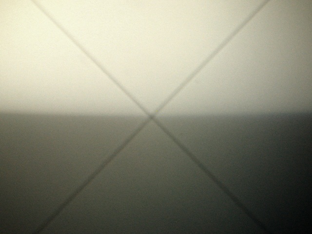
| A view through the focusing telescope with compensation, both Amici prisms replaced thus no rainbow colour along the boundary line making it easy to set cross lines at the exactly defined boundary. | ||||||||||||
|
Unfortunately camera introduced some hue, and it did not focus properly so capture does not show what is observed with a bare eye. When observing by eye through the focusing telescope boundary line is clearly defined separating bright, evenly lit area from evenly lit light-grey area, nothing like what is captured by the camera, the image above. |
||||||||||||
|
|
||||||||||||
|
||||||||||||
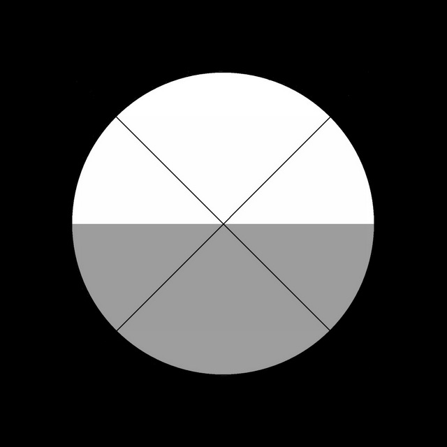
| Drawing above shows the actual appearance of the image as seen through the focusing telescope | ||||||||||||
|
||||||||||||
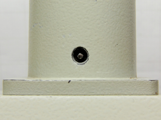
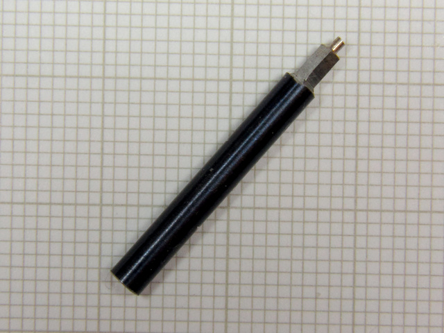
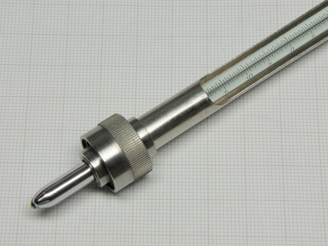
| Calibration adjustment screw with specially shaped head, a male 1.30 mm square | ||||||||||||
|
To calibrate Abbe Refractometer it is necessary to fine adjust position of one lens in relation to the light path, lens itself being part of the focusing telescope system, by setting the screw found in the base of the focusing telescope itself, shown above. To accomplish this task a special wrench is needed, of course it was missing, so to be able to do the calibration it was necessary to make the wrench. I made it out of brass hexagon stock 5.0 mm AF, the square hole was made with a steel punching tool specially made to fit the screw head. |
||||||||||||
|
||||||||||||
| Punch tool used to make a square hole. Note a round nose piece which actually is a guide pin | ||||||||||||
|
||||||||||||
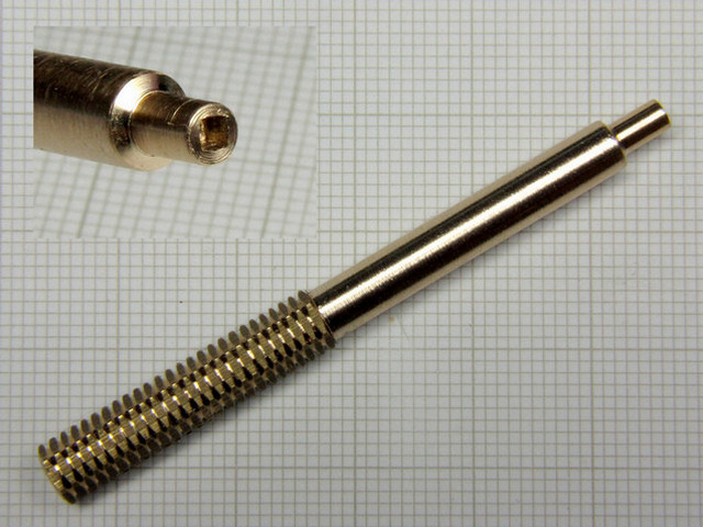
| Calibration Adjustment Wrench | ||||||||||||
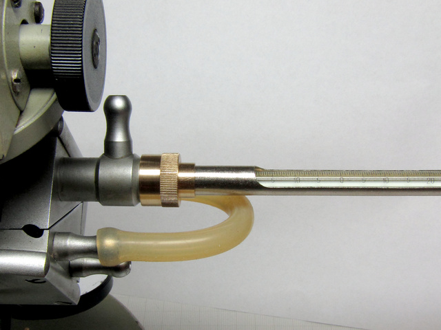
| Prior to commencing calibration there was need to replace the missing thermometer because refractive indices change as does the ambient temperature and because refractometer errs with the change of temperature at rate of 0.00045 per 1º C. Refractometer is normally equipped and supplied with a thermometer that mounts directly on to the measuring prism enclosure. The enclosure itself is designed as a two part heat exchange block connected to each other by a rubber pipe. The upper block encompassing the measuring prism and the lower block encompassing the illuminating prism, both blocks are provided with connections to allow water flow to and from cooling/heating unit to keep the measuring prism at the constant temperature to ensure that readings are taken accurately at 20ºC ±0.2ºC. | ||||||||||||
|
| ||||||||||||
|
Hovering the mouse over the image will show second image with prism assembly open. Image above shows the prism assembly closed, it also shows water inlets and outlets with the thermometer receptacle acting as the final water outlet. | ||||||||||||
|
| ||||||||||||
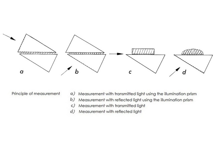
|
This prism arrangement allows several types of measurement to be taken. Drawing above shows the four distinct measurement types possible with this refractometer, of both, liquids and solids. | ||||||||||||
| If index of refraction was determined at temperature different than that reported in the literature then there is need to correct value for the temperature variation before comparing it to the value found in literature. | ||||||||||||
| Corrected index of refraction nD20 can be calculated by the use of the following formula: | ||||||||||||
|
nD20
=
nDt
+
α | ||||||||||||
| ||||||||||||
| If the temperature coefficient α of the specimen is not known then assumed value of α = 0.00045 can be used relying on the observation that the temperature variation in the index of refraction is similar for many organic liquids, however this correction for α is only approximate and should not be used for aqueous solutions. Perhaps it ought to be noted that presence of impurities in specimen can significantly change index of refraction of substance, thus it is fairly safe to assume that anything within ± 0.002 of the value found in literature is a satisfactory match. | ||||||||||||
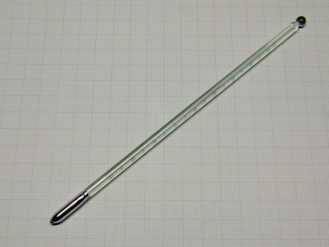
| For completing refractometer restoration there was need to provide it with temperature measuring function. Not an easy task as the thermometer was missing together with the protective sleeve and the mounting nut, the lot. I've searched my stock of materials and have found suitable thermometer, a fast response laboratory type thermometer covering range -30ºC to 50ºC, graduated in 0.5º and 190 mm long, body 160 mm and mercury reservoir 30 mm long and OD 5.5 mm. The only other choice was a similar thermometer with range of 0ºC - 55ºC, smallest division of scale also 0.5ºC but fair bit shorter, 140 mm total, the scale also shorter by 15 mm than the other thermometer so the choice between the two was rather easy. | ||||||||||||
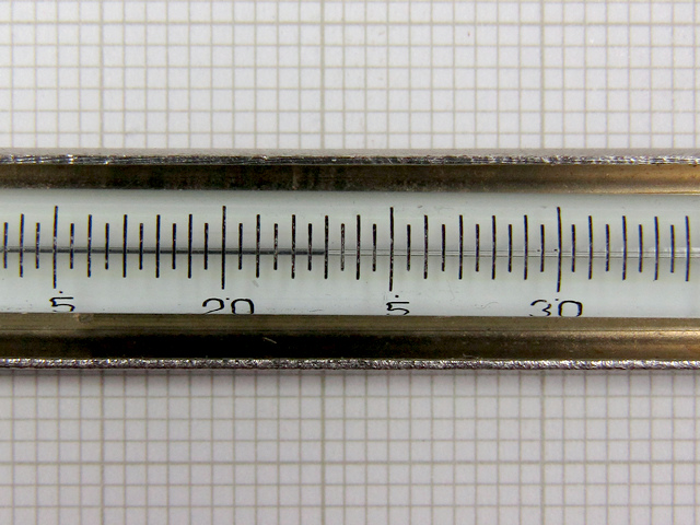
| This type of laboratory thermometers are quite accurate, each individually calibrated by engraving graduation markings on the thermometer's outer surface, 10ºC scale is over 15 mm in length, thus the 0.5ºC division is equal to or larger than 0.75 mm of the scale length, e.g. width of the graduation marks on the thermometer scale is 0.12 mm. Measurement error is less than 0.2ºC at any part of the scale guaranteed by the manufacturer, each thermometer is packed accompanied with a certificate and calibration listing. | ||||||||||||
|
| ||||||||||||
|
Laboratory type fast response thermometer | ||||||||||||
|
| ||||||||||||
|
Graduation markings are spaced so that one can easily estimate temperature reading down to 0.1ºC with error not larger than ± 0.1ºC, well within the specs of the refractometer. | ||||||||||||
|
|
||||||||||||
|
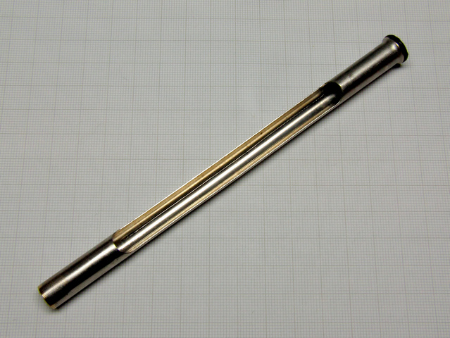
Brass protective sleeve |
||||||||||||
| My junk box provided a nice protective brass sleeve with bright and shiny coating of both surfaces, with no tarnish whatsoever, the inner surface furnishing plenty of reflected light to increase contrast and allow easy readings. Brass sleeve was too long so I have shortened it by cutting off 25 mm of its length. The OD is 10.0 mm and wall thickness 0.55 mm, a bit larger than actually needed for the thermometer that I intend to use. As there is a problem finding a suitable thermometer, of the correct diameter, length, measuring range and of required resolution, one has to make a number of compromises in order to get job done however all characteristics must remain within the limits dictated by the refractometer specs. | ||||||||||||
|
|
||||||||||||
|
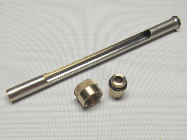
The protective sleeve with mounting parts |
||||||||||||
| To be able to use the protective sleeve I have found, I needed to make mounting bushing for the sleeve that will also hold thermometer and at the same time be water tight to allow cooling/heating liquid flow without leaks. Next thing was to make a nut used for holding the whole works, the only example I have is the refractometer receptacle and few images of the refractometer of the same type which allowed me to fashion my new nut after the original. Measurement taken from the refractometer receptacle told me that the thread is Metric, major diameter 15.0 mm and pitch 0.75 mm. | ||||||||||||
|
|
||||||||||||
|
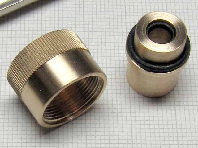
The new thermometer mounting nut with part of its surface knurled to allow firm grip next to the protective sleeve bushing with O-rings in place |
||||||||||||
| To achieve water tightness I used two O-rings, thoughtfully placed at the right spots they provide a no leak mounting of the thermometer assembly as well as the elastic coupling to the thermometer without danger of braking its glass envelope. | ||||||||||||
|
|
||||||||||||
|
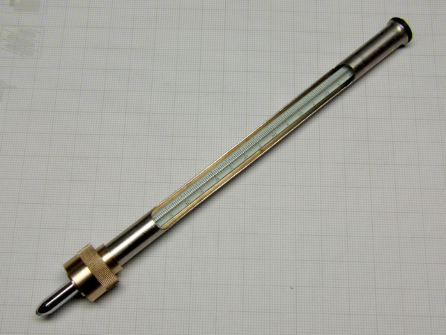
Thermometer assembled in its new protective sleeve with water tight bushing and mounting nut |
||||||||||||
| Two more O-rings placed on the thermometer body inside the enclosed sections of the protective sleeve give additional protection by keeping distance between the thermometer and inner surface of the brass protective sleeve. Perhaps not necessary as the thermometer non working end, one with the glass ball, is nested in a rubber bushing closing the sleeve visible on top. | ||||||||||||
|
|
||||||||||||
|
Thermometer in its place, securely mounted and ready to be used |
||||||||||||
|
|
||||||||||||
| As a final touch, after some experimenting, I have managed to nickel plate newly made parts for the thermometer and refractometer employing simple DIY process, using home brew acid based electrolyte (without any of the highly poisonous compounds such as KCN etc.). The first attempt failed, followed with a two step process. The first step was copper plating the parts then after cleaning followed with three consecutive nickel layers with only a rinse and light buffing in between to check the evenness of plating. | ||||||||||||
|
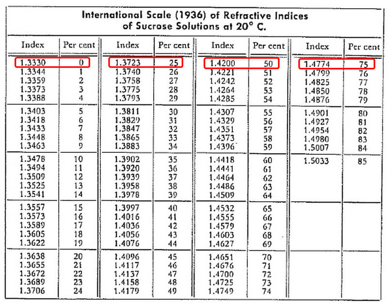
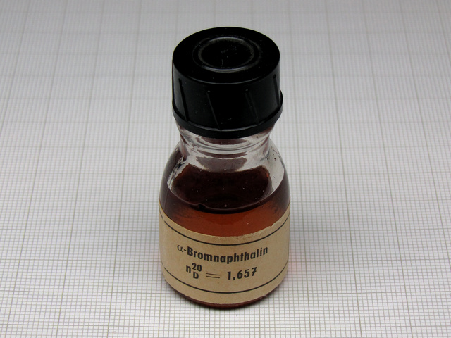
The final step left to perform was calibrating the refractometer using α-bromonaphtalene, which has refraction index of exactly 1.660 at 20º C. As an additional check of calibration, suggested to me by Randall Buck, I have made aqueous solution of sugar in three different concentrations: 25%, 50% and 75% which I then filtered twice to remove presence of any particles that may have found their way in. I then measured the RI of the re-distilled water and RI of the three sugar solutions and compared them to the corresponding RI values from the table. |
||||||||||||
|
|
||||||||||||
|
The results read by refractometer were accurate right down to the fourth decimal place making me very happy with the results of the Abbe Refractometer repair which clearly is performing within its specification: +/- 1x10⁻⁴ - 2x10⁻⁴. 1 |
||||||||||||
|
||||||||||||
|
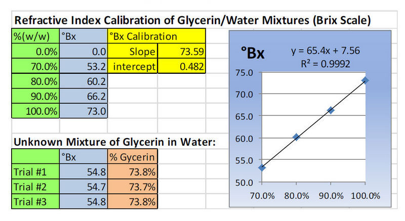
"Calibration of the refractometer is important. While published values are helpful, it is critical to insure the instrument is measuring values correctly. Liquid solutions are prepared or purchased that are measured under the same conditions as the samples. Here is an actual example of a test for glycerine (glycerol) in water. Four standards were prepared by weighing out the appropriate masses of glycerine and water, preparing concentrations of 70%, 80%, 90%, and 100% (w/w). These were measured on the Abbe refractometer on a cold day in the lab and the values differ slightly from the published values." 3 |
||||||||||||
|
|
||||||||||||
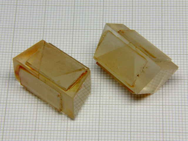
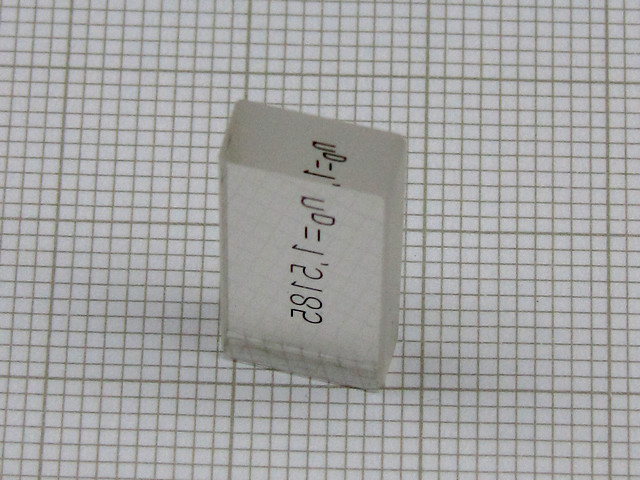
| There is, of course, another method that can be used to accurately calibrate refractometer, providing that within accessories supplied with refractometer there is a small glass calibration plate, as is shown below. | ||||||||||||
|
| ||||||||||||
| These calibration plates are made of stable, optical quality glass, with refraction index engraved onto the frosted surface. One can use it to check refractometer for accuracy and recalibrate it if and when necessary. To do so one has to use immersion fluid with index of refraction higher than is the refraction index of the glass plate, e.g. α-bromonaphtalene (nD=1.657) to bridge the calibration plate to measuring prism, and then proceed with measurement accomplished using reflected light. The calibration plate is specially prepared, all but two of its surfaces are frosted. | ||||||||||||
|
| ||||||||||||
|
Two surfaces that are used for measuring are highly polished and are perpendicular to each other, larger one is bridged to refractometer's measuring prism and the smaller one faces the illuminator. | ||||||||||||
|
| ||||||||||||
| Another thing that I plan for doing in the near future is to design a temperature controller with sensor mounted inside the measuring prism enclosure, and a unit containing small heat exchanger with Peltier cell and a small pump to circulate water and enable cooling of the measuring prism enclosure and keep it at the constant temperature of 20º C for repeatable and accurate measurements. | ||||||||||||
|
| ||||||||||||
| References: | ||||||||||||
|
1. User's manual - Abbe Refractometer Type G - Carl Zeiss Jena | ||||||||||||
|
2. Refractive Indices and Densities of Aqueous Solutions of Invert Sugar - National Bureau of Standards | ||||||||||||
|
3. Refractive Index - an article found on web - no author named to give credit to | ||||||||||||
|
4. CZJ Abbe Refraktometer Modell G - Gebrauchsanleitung - 32-G11Ob-1 | ||||||||||||
|
5. Dispersionstafel "F4" zum Abbe-Refractometer - 32-T110b-1 | ||||||||||||

| ||||||||||||
| Published in the June 2013 edition of Micscape Magazine. | ||||||||||||
| www.micscape.org | ||||||||||||
|
|

|
Get Web Counter |
|
|