| Power LED Driver | ||||||||||||||||||||||||||||||||||||||||||||||
| By Dushan Grujich, on February 14th. 2014 | ||||||||||||||||||||||||||||||||||||||||||||||
| ||||||||||||||||||||||||||||||||||||||||||||||
|
Most often microscope enthusiasts encounter a problem when converting their microscope illuminator from incandescent lamp to a power LED. Problem is usually in a choice of DC power source that is needed to supply LED as the incandescent lamp illuminators are powered by AC most often without provision of changing brightness intensity. LED-s are current devices, hence the need of limiting the current to control brightness. Currently there is a number of small low cost high efficiency DC-DC converters which were originally designed for use as chargers for various types of rechargeable battery cell packs such as NiCd, NiMH and Li Polymer. Some of these modules are capable of working as variable constant current chargers and can be used as LED drivers. | ||||||||||||||||||||||||||||||||||||||||||||||
| ||||||||||||||||||||||||||||||||||||||||||||||
|
| ||||||||||||||||||||||||||||||||||||||||||||||
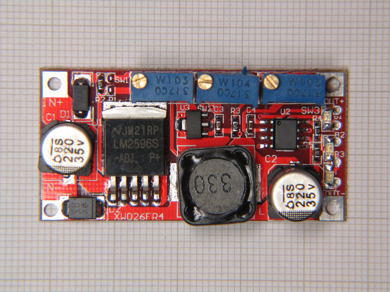
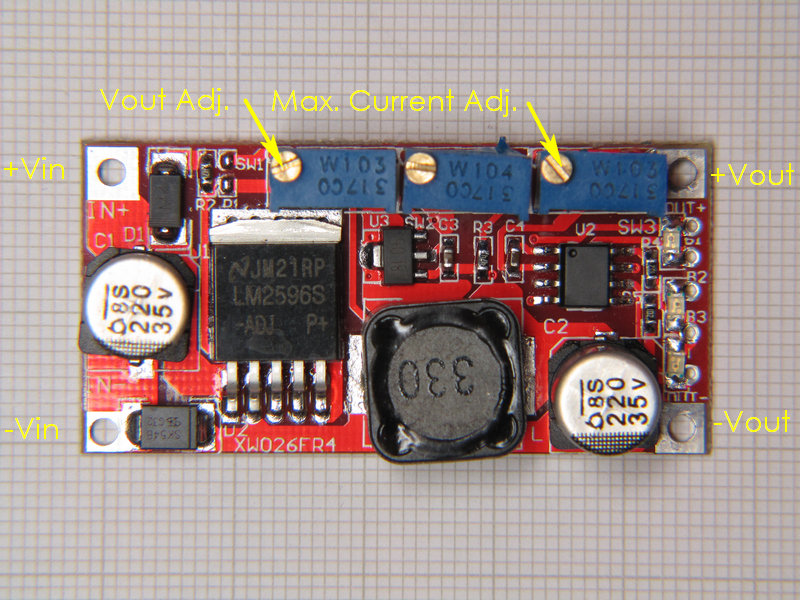
| Module capable of sourcing constant current | ||||||||||||||||||||||||||||||||||||||||||||||
|
According to manufacturer this module is capable of delivering 15 W of power at a maximal current of 3 Amps, capable of sourcing constant current. Practically ideal for use to drive LED-s of 3 - 10 Watt power. | ||||||||||||||||||||||||||||||||||||||||||||||
| ||||||||||||||||||||||||||||||||||||||||||||||
|
Image above shows connection terminals and locations of the trim-pot adjustments | ||||||||||||||||||||||||||||||||||||||||||||||
|
| ||||||||||||||||||||||||||||||||||||||||||||||
|
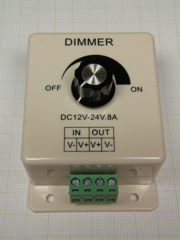
The insides of the dimmer box before modification | ||||||||||||||||||||||||||||||||||||||||||||||
|
| ||||||||||||||||||||||||||||||||||||||||||||||
|
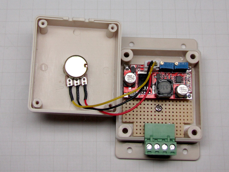
The insides of the dimmer box after modification | ||||||||||||||||||||||||||||||||||||||||||||||
| I have mounted module on a piece of prototyping PCB, and mounted it into the Dimmer box. Module was modified only by removal of the 10 k Ohm Voltage adjustment trim-pot and replaced with 1 k Ohm potentiometer that was part of the original dimmer circuit. The new 1 k Ohm value provides intensity control from zero to full brightness, allowing output voltage change from 1.25 V to approximately 4 V. | ||||||||||||||||||||||||||||||||||||||||||||||
| The maximal output current is limited by adjusting trim pot SW3 to whatever the maximum rating of the LED is. Thus the circuit operates in variable voltage mode 1.25-4.0 V until the current reaches allowed maximum, it then changes the operating mode to constant current. For other values of Voltage out, one should choose value of the potentiometer other than the 1 kOhm. The choice can be determined experimentally, by using the 10 kOhm trim-pot (it is connected as a variable resistor, not as potentiometer, see circuit diagram) to set voltage output to a needed level, then disconnect power and measure resistance of the trim-pot. Measured resistance value should now be resistance of the potentiometer, of course pots are manufactured with resistance preferred values, so one should choose the first lower preferred value and add a fixed resistor in series to reach needed resistance. | ||||||||||||||||||||||||||||||||||||||||||||||
|
Driving LED with variable constant current source, if not limited by some means, requires current monitoring while setting. Perhaps a panel meter, otherwise one can allow too much current to flow and burn out the LED. Thus, in order to have some sort of protection, I decided to vary the voltage and instead of monitoring current I have used the current setting trim pot to limit the output current to a maximum allowable so that current cannot be increased above the limit by varying voltage, no need for current panel meter. | ||||||||||||||||||||||||||||||||||||||||||||||
| One should keep in mind that under certain circumstances it may be necessary to be able to set the LED brightness at some exact value, as was perhaps done at some instance in the past, so this is when a panel meter indicating current level flowing through the LED is needed. | ||||||||||||||||||||||||||||||||||||||||||||||
| There is large number of possible choices of DC power sources. One can use the low cost Wall Wart power adaptor rated at least 20 Watt with any voltage output between 7 and 35 Volts, or even one of the switch mode lab power supplies that have appeared on the market in the recent years with cost lower than the cost of parts needed for making one. Total cost of this power LED driver should not exceed $10, plus cost of suitable wall wart, they start on eBay as low as $5, so total cost should not go above $20. Most components bought on eBay are usually shipped free. | ||||||||||||||||||||||||||||||||||||||||||||||
| Parts required: | ||||||||||||||||||||||||||||||||||||||||||||||
|
||||||||||||||||||||||||||||||||||||||||||||||
|
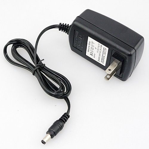
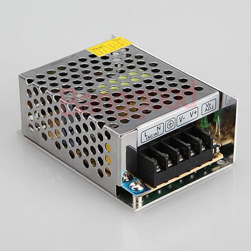
Of course, any DC power source can be used as long as the voltage output is within the range of 7-35 V and power rating is more than 20W, such as one shown below, available on eBay. |
||||||||||||||||||||||||||||||||||||||||||||||
|
||||||||||||||||||||||||||||||||||||||||||||||
| Typical Wall Wart 110/240VAC to 12VDC rated 2 Amps. | ||||||||||||||||||||||||||||||||||||||||||||||
|
||||||||||||||||||||||||||||||||||||||||||||||
|
WARNING: The above
pictured unit is mains operated. Seller does NOT provide installation
instructions, wiring cable, ON/OFF switch, or screws.
Installation should be performed by a qualified electrician. |
||||||||||||||||||||||||||||||||||||||||||||||
|
Due to a concern that there may be too much heat generated within the small dimmer box, which practically is hermetically sealed, I have tested module at continuous output current of 1.5 A at 3.80 V, module inside of the closed box. Module was operating cool during 24 hour test. It worked at efficiency of 86 %, input voltage to the module 12.0 V @ 0.55 A i.e. 6.6 W, output was 3.80 V @ 1.5 A load i.e. 5.7 W, thus losses were only 900 mW so the heat generated cannot really be harmful. Temperature within the box did not exceed 38º C (~100º F), monitored for the duration of the test with the ambient temperature of 23º C (73º F). |
||||||||||||||||||||||||||||||||||||||||||||||
| Even with the efficiency down to 75 %, losses are less than 2 W, being about 1.65 W. In conclusion, I can say that there ought not be worry as long as losses, dissipated as heat, are kept at or under 2 W. For any higher power use, one may consider larger box with some sort of ventilation, and in case of need to drive LED at high power lasting long, then module should be mounted to some sort of heat sink. Keep in mind that loading module with more than 3 A may prove to be harmful to it, heat sink or not. | ||||||||||||||||||||||||||||||||||||||||||||||
|
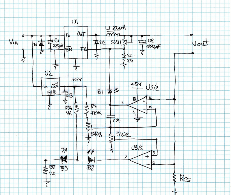
For those who might wish to use this module in perhaps some other arrangement, below is circuit diagram with parts list. |
||||||||||||||||||||||||||||||||||||||||||||||
|
| ||||||||||||||||||||||||||||||||||||||||||||||
|
Circuit diagram of DC-DC converter module | ||||||||||||||||||||||||||||||||||||||||||||||
| Parts of module: | ||||||||||||||||||||||||||||||||||||||||||||||
| ||||||||||||||||||||||||||||||||||||||||||||||
| References: | ||||||||||||||||||||||||||||||||||||||||||||||
| 1. LM2596S-ADJ Datasheet - National Semiconductor, May 2002 | ||||||||||||||||||||||||||||||||||||||||||||||
|
PDF version of the article: Power LED Driver | ||||||||||||||||||||||||||||||||||||||||||||||
|
| ||||||||||||||||||||||||||||||||||||||||||||||
| top | ||||||||||||||||||||||||||||||||||||||||||||||

| ||||||||||||||||||||||||||||||||||||||||||||||
| ||||||||||||||||||||||||||||||||||||||||||||||
|
| ||||||||||||||||||||||||||||||||||||||||||||||
|
|
||||||||||||||||||||||||||||||||||||||||||||||
|
||||||||||||||||||||||||||||||||||||||||||||||