| A simple, low cost, conversion of incandescent-lamp illuminator to a power LED | ||||||||||||||||||||||||||||||||||||||||||||||
| By Dushan Grujich, on October 15th. 2012 | ||||||||||||||||||||||||||||||||||||||||||||||
|
| ||||||||||||||||||||||||||||||||||||||||||||||
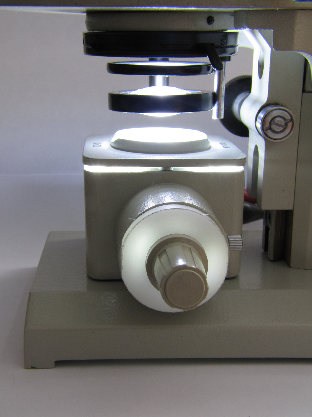
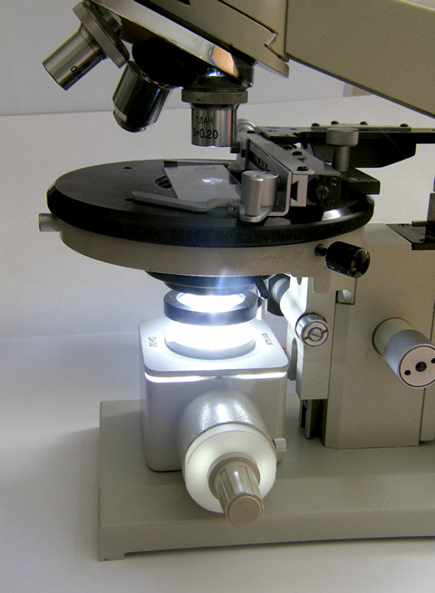
| Fig. 1 - Completed conversion with illuminator in use | ||||||||||||||||||||||||||||||||||||||||||||||
|
My LOMO Biolam 70 has come with the OI-32 illuminator using a 220V AC 15W
incandescent-lamp, which, when used for longer period gets very hot to the
touch. This situation had me thinking of replacing incandescent-lamp with a
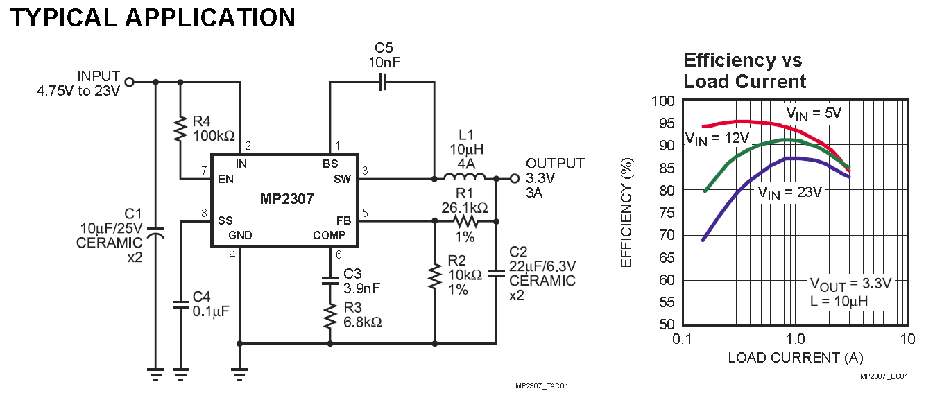
power LED. My experimenting with power LEDs resulted in permanent conversion of the OI-32 illuminator. To drive the power LED I have used a low cost 10 W DC-DC Step Down Converter, KIS-3R33S module, capable of delivering up to 3A continuously. This module comes with output voltage preset to 3.3V. However, it is easy to readjust and have output set at any voltage from 1.21 V - 10.43 V, if the circuit is modified then the output voltage can be varied up to 20V. | ||||||||||||||||||||||||||||||||||||||||||||||
| ||||||||||||||||||||||||||||||||||||||||||||||
| ||||||||||||||||||||||||||||||||||||||||||||||
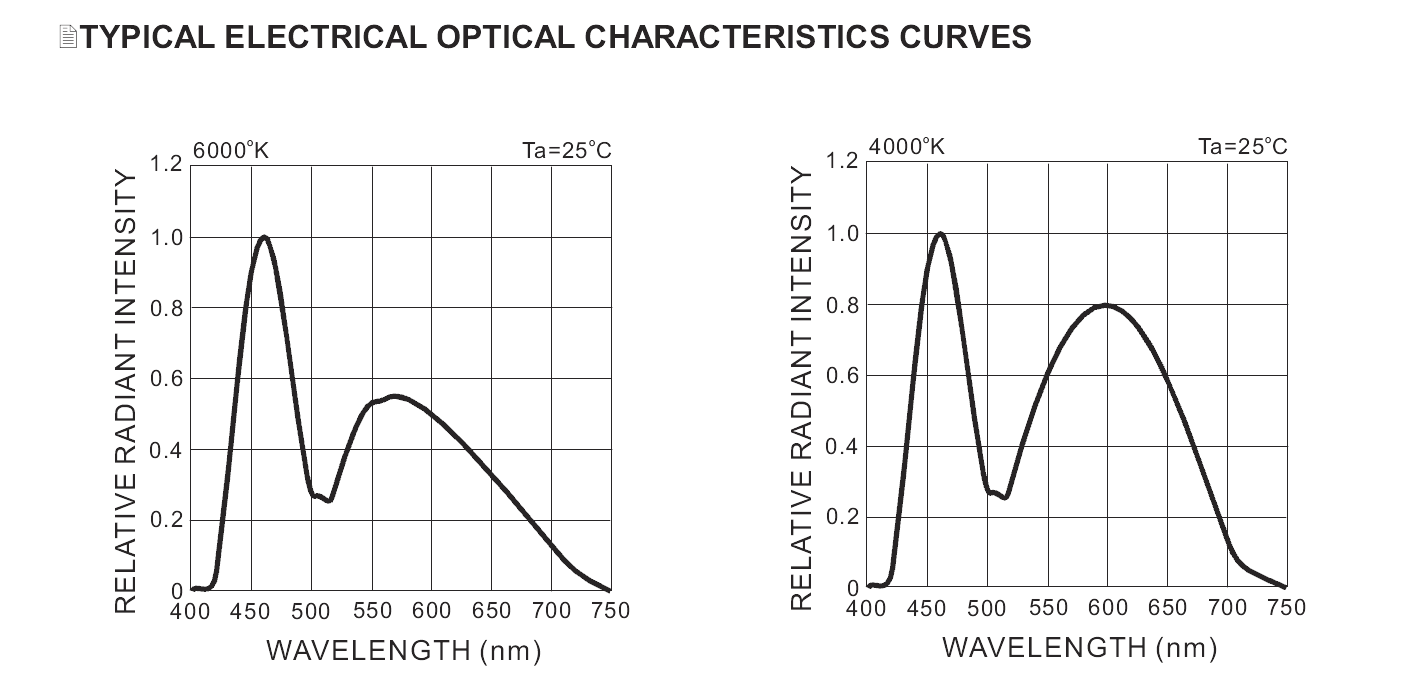
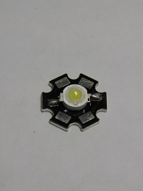
| The final choice was 1W "Pure White" 150 lm LED with colour temperature of 6000º K, replacing 15 W lamp rated 90 lm at 230 VAC, which burns out too often due to excessive heat. | ||||||||||||||||||||||||||||||||||||||||||||||
|
Different LEDs from different manufacturers operate at different maximum
continuous voltage, which in turn determines the maximum current flowing
through the LED. To protect LED and to provide stable light characteristics it
is necessary to limit the voltage output from the KIS-3R33S module according
to the specific requirements for each type of power LED, as specified by the
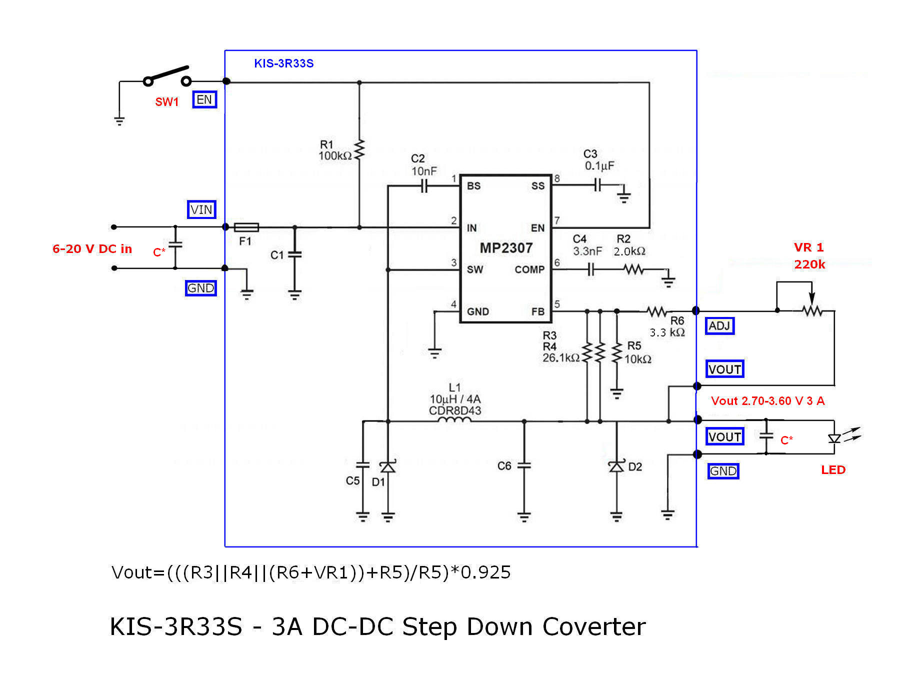
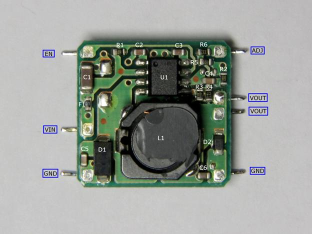
manufacturer. For power LEDs, which I have used, manufacturer has specified maximum continuous forward voltage at 3.6 V for 150 lm one-watt LED, HPB8-49KWHB, and 3.7 V for the 235 lm three-watt LED HPB8b-49K3WHB. Following manufacturer's instructions, I have limited the maximum output voltage of the module so that it will suit either of the two LEDs. I also wanted to have the means of continuous brightness adjustment so I used a potentiometer to vary the brightness. Necessary modification of the module consisted in removal and replacement of three SMD resistors, done as follows. The module is very small, measuring 21x22x10 mm total. To modify it one must remove the bottom cover and then remove module from its housing, not difficult, the cover is snap-on type. Resistors R3, R4 (both marked 513 i.e. 51 k Ohm) and R6 (marked 332 i.e. 3.3 k Ohm) should be removed, and replaced. R3 and R4 with 39 k Ohm and 180 k Ohm (order of placement is unimportant as they are connected in parallel). Resistor R6 should be replaced with one of the 51 k Ohm resistors removed from R3 or R4 positions. The additional components are the logarithmic tracking potentiometer VR1 220 k Ohm (470 k Ohm if 3W LED is used to bring up output voltage to 3.7 V), connected externally, and optionally a switch can be connected from ground GND (marked on circuit diagram and component layout) to terminal EN which when switch is engaged turns off the DC-DC converter. The two ceramic capacitors, 10uF /25V, one should be connected across VIN and GND and another across VOUT and GND. The value of the resistor R6, chosen to prevent voltage output falling below 2.70 Volts as below that value LED will cut off. Combination of resistors R3, R4, R5, R6 and VR1 determines the output voltage according to the following formula: Vout = (((R3||R4||(R6+VR1))+R5)/R5)*0.925 Resistors R3, R4, R6+VR1 (R6 is connected in series with VR1) are connected in parallel and are actually acting as one resistor. To calculate value of two or more resistors in parallel: Rx=1/(1/R1+1/R2+1/Rn) in our case Rx=1/(1/R3+1/R4+1/(R6+VR1)) so Vout becomes: Vout = (Rx+R5)/R5)*0.925 (where R5 stays unchanged, as is, 10 k Ohm) LED is mounted onto simple carrier made from 1 mm thick aluminum sheet, which also serves as heat sink, it easily mounts inside the body of the OI-32 (no modifications to the OI-32 housing were needed). Carrier is so constructed to place LED at the exact place where the incandescent lamp filament was. I mounted power module unit on a small piece of proto-board and fixed it onto the bottom side of the carrier, under the LED. In order to close the opening where the incandescent lamp was located originally, I have machined a "plug" out of Delrin (Polyoxymethylene) and mounted the potentiometer inside it. To improve overall performance of the illuminator and to achieve even more flat and uniform illumination, it was suggested to place a ground glass filter just above the LED. Note: If LED flicker is experienced, then the 'Soft Start' capacitor C3, part of the module, should be removed. References: 1. HPB8-49KxWHBx data sheet - HUEY JANN ELECTRONICS INDUSTRY CO., LTD.
| ||||||||||||||||||||||||||||||||||||||||||||||
| Parts required: | ||||||||||||||||||||||||||||||||||||||||||||||
| ||||||||||||||||||||||||||||||||||||||||||||||
| References: | ||||||||||||||||||||||||||||||||||||||||||||||
|
1. HPB8-49KxWHBx data sheet - HUEY JANN ELECTRONICS INDUSTRY CO., LTD. 2. HPB8b-49K3xWHBx data sheet - HUEY JANN ELECTRONICS INDUSTRY CO., LTD. 3. MP2307_r1.9 data sheet - Monolithic Power Systems, Inc. | ||||||||||||||||||||||||||||||||||||||||||||||
| ||||||||||||||||||||||||||||||||||||||||||||||
| ||||||||||||||||||||||||||||||||||||||||||||||
| Fig. 2 The component layout | ||||||||||||||||||||||||||||||||||||||||||||||
| ||||||||||||||||||||||||||||||||||||||||||||||
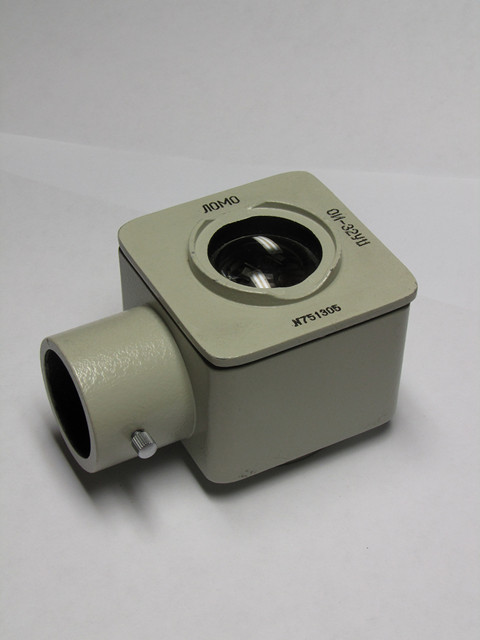
| Fig. 3 OI-32 Illuminator shown without lamp assembly | ||||||||||||||||||||||||||||||||||||||||||||||
| ||||||||||||||||||||||||||||||||||||||||||||||
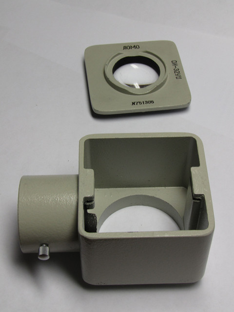
| Fig. 4 Condenser plate removed | ||||||||||||||||||||||||||||||||||||||||||||||
| ||||||||||||||||||||||||||||||||||||||||||||||
| Fig. 5 1W LED | ||||||||||||||||||||||||||||||||||||||||||||||
| ||||||||||||||||||||||||||||||||||||||||||||||
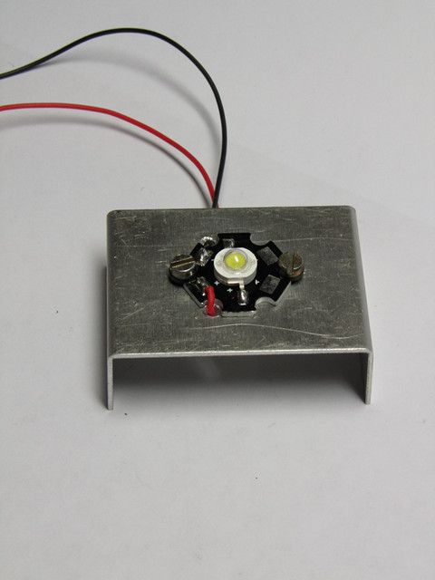
| Fig. 6 the 1W LED mounted onto the carrier/heat sink | ||||||||||||||||||||||||||||||||||||||||||||||
| ||||||||||||||||||||||||||||||||||||||||||||||
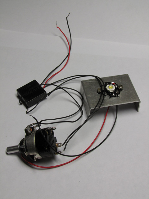
| Fig. 7 driver module and LED wiring while testing | ||||||||||||||||||||||||||||||||||||||||||||||
| ||||||||||||||||||||||||||||||||||||||||||||||
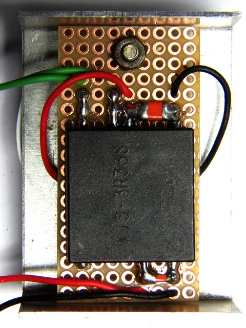
| Fig. 8 Driver module mounted on proto board, onto the bottom side of the carrier/heat sink | ||||||||||||||||||||||||||||||||||||||||||||||
| ||||||||||||||||||||||||||||||||||||||||||||||
| Fig. 9 LED assembly mounted and centred inside the illuminator housing | ||||||||||||||||||||||||||||||||||||||||||||||
| ||||||||||||||||||||||||||||||||||||||||||||||
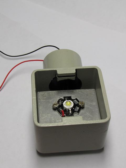
| Fig. 10 Illuminator finished and placed in its cradle with a pot mounted in a Delrin plug ready for use | ||||||||||||||||||||||||||||||||||||||||||||||

| ||||||||||||||||||||||||||||||||||||||||||||||
| Published in the November 2012 edition of Micscape Magazine. | ||||||||||||||||||||||||||||||||||||||||||||||
| www.micscape.org | ||||||||||||||||||||||||||||||||||||||||||||||