| Abbe's Plate for Testing Objective Aplanatism | ||
| A DIY version | ||
| By Dushan Grujich, on May 22nd. 2013 | ||
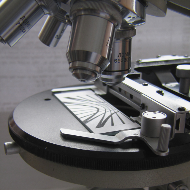 | ||
| Ernst Abbe's Aplanatism Test Plate in use | ||
|
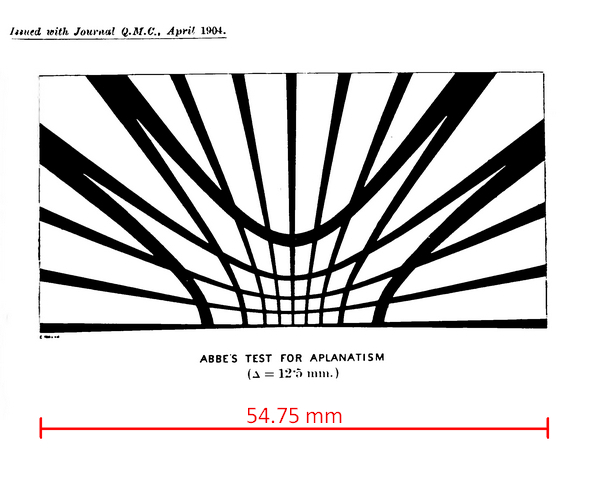
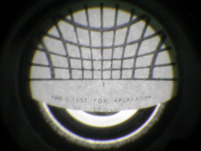
Using the Abbe-Helmholtz sine law Ernst Abbe designed the aplanatism test plate2 in 1879 in order to check how well corrected were objectives produced prior to the formulation of the sine law. The principle of use is simple, test plate is placed flat on the microscope object stage, focused and centred at exactly the middle of the base line relative to the light axis of the microscope. Then, the objective should be raised 12,5 mm, the eyepiece replaced with the phase-contrast telescope and focused on to the upper focal plane. The curved lines of the test plate should cover half the area of the upper focal plane. Depending on the amount of the objective correction test plate lines should appear as straight lined net. The particular design of the test plate has instigated professor Frederic J. Cheshire to devise the apertometer that could be read from the upper focal plane directly by use of the phase contrast telescope. The Cheshire apertometer1 was described in article published in the April 2013 edition of Micscape Magazine.7 | ||

Use mouse right click and "view image" to download drawing in higher resolution |
||
| Ernst Abbe's Plate for testing objective aplanatism | ||
|
| ||
|
||
|
With all details worked out I got on with making test plate by printing it with a laser printer on a sheet of white paper. It took several iterations to get the correct size of the image, which I then glued on to a glass slide for easier manipulation. |
||
|
| ||
|
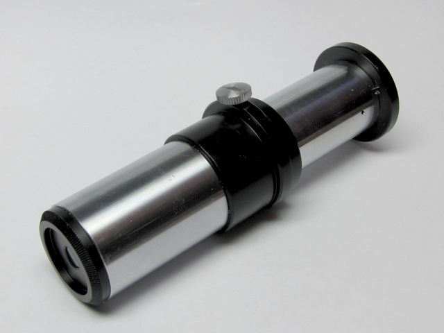
A PC Telescope which I have used to observe upper focal plane of the objectives tested | ||
|
| ||
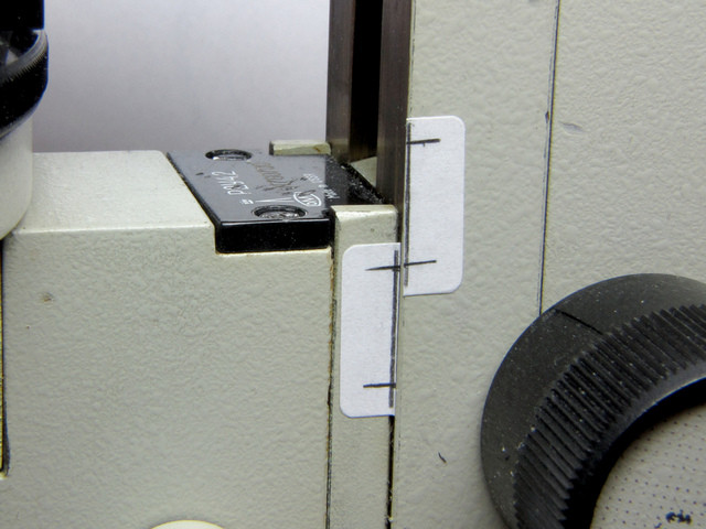
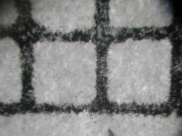
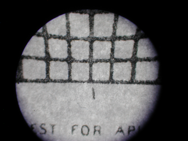
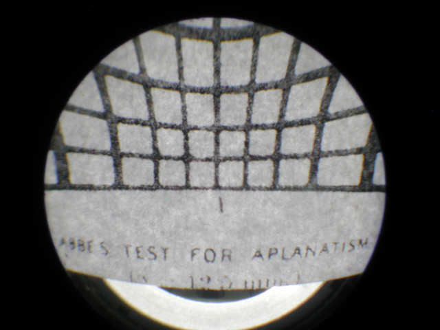
| The means of fast and accurate marking of distance for raising the objective above the aplanatism test plate for the chosen value of delta, 12.5 mm, is shown at the image above. The rest was easy, with the help of the PC telescope and Nikon CP 990 I have taken shots of the images formed in the upper focal plane of the objectives tested, just as seen by eye viewing through the PC telescope. | ||
|
|
||
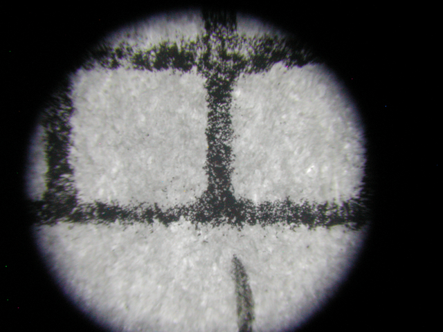
| LOMO Achromatic 8/0.20 160/- designation M-42 | ||
|
||
| LOMO Plan Achromatic 9/0.20 160/- designation OM-2 | ||
|
||
| LOMO Achromatic 20/0.40 160/- designation OM-27 | ||
|
||
| LOMO Achromatic 40/0.65 160/0.17 designation OX-1 | ||
|
||
| LOMO Achromatic 90/1.25 160/0.17 designation OM-41 | ||
| References: | ||
| ||

| ||
| Published in the August 2013 edition of Micscape Magazine. | ||
| www.micscape.org | ||