|
Last update January 12th. 2020 |
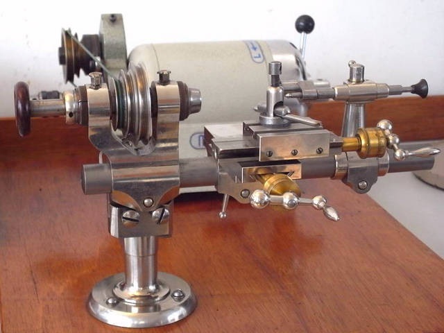
'D-bed' 8 mm Watchmaker's Lathe Lorch, Schmidt & Co. November 25th. 2016 |
|
The most recent acquisition for my workshop is an 8 mm, watchmaker's D-bed
lathe.
Lorch, Schmidt & Co., one of the top German tool makers, have designed and built it. |
 |
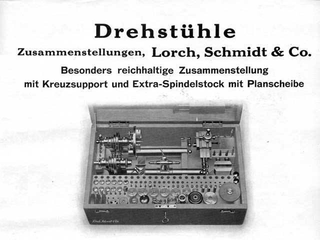
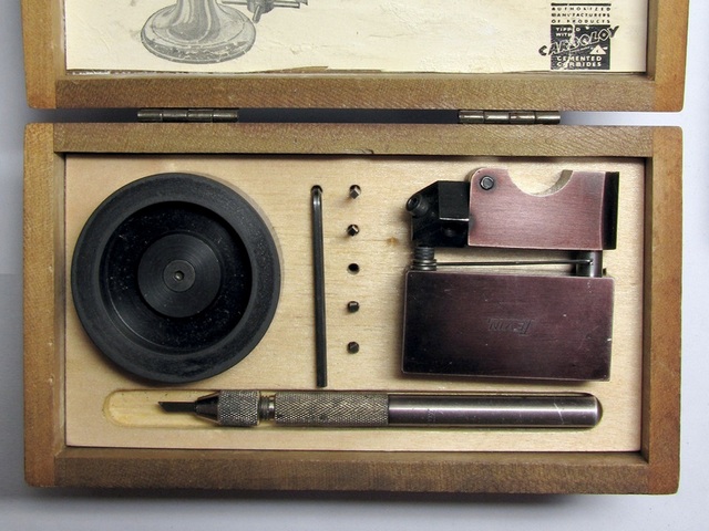
| The 8 mm
Lorch lathe boxed as it used to be supplied when new. My lathe,
unfortunately, came without the walnut wood box.
However, it came with all the accessories as shown in the image, with a few extras. As it says in the 1937 ad: "Lathe set, Lorch, Schmidt & Co. Especially enriched with the cross slide and extra headstock with faceplate." |
|
|
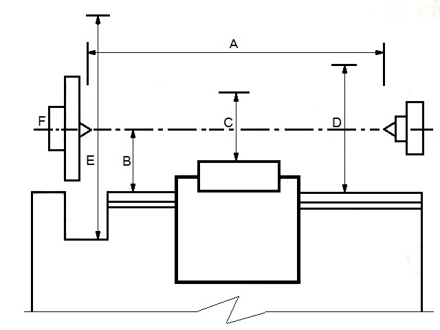
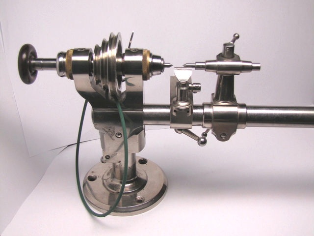
Basic specification of the lathe, with bed 250 mm long, is as follows:
A - between centres distance 120 mm B - centre height 40 mm C - swing diameter above the top/cross slide 14/48 mm D - swing diameter over bed 80 mm E - swing diameter with the gap-bed 140 mm F - Maximum bar diameter through the spindle 5 mm Bed diameter 20 mm/17 mm as shown in the second image. |
 |
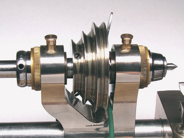
| One of the first tests that I performed, before taking any measurements, was alignment of headstock and tailstock by use of the razor blade, result is as shown on the images. | 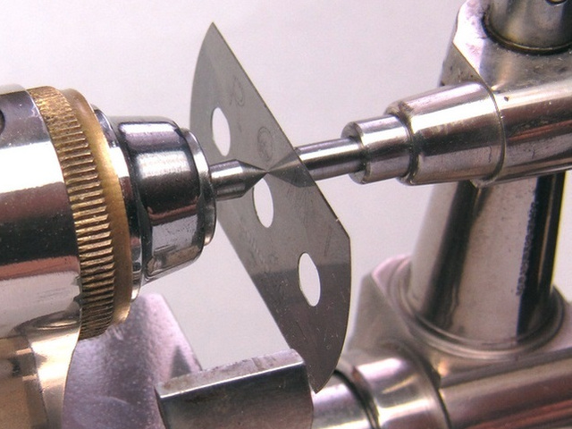 |
| Keeping
in mind, that the lathe was bought new in late 1930's by the previous
owner, then worked with the next sixty odd years, and after its owner
passed away, lathe sat unused additional twenty years, yet preserved in a
remarkable condition.
Of course, there are a few small spots of surface rust appearing here and there through the nickel plating, nothing in any sense alarming, and by no means impairing its present, or future use. Obviously, it has been well taken care of. |
 |
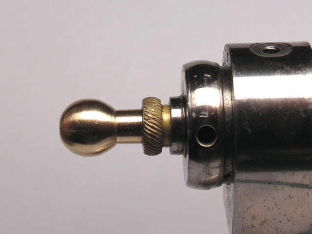
| There were few small pieces missing, the pump centre ball knob on the back of faceplate headstock, and one Faceplate Dog Nut Washer, both shown on the image. | 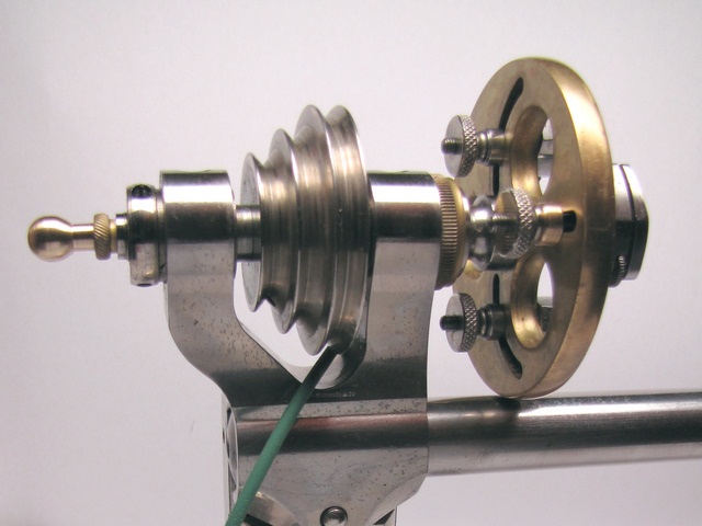 |
| The
newly made replacement of the missing Pump Centre Ball Knob, and in the
second image Faceplate Dog Nut Washer.
Having turned Ball Knob with only a graver and T-rest, not as yet having made tool for ball turning, I am actually quite pleased with the way it turned out. |
 |
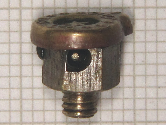
| Other
things missing are the headstock oilers i.e. the oil hole caps. When I
received the lathe, only one cap was present.
If nothing else, it serves the purpose of identifying the maker, and if still in business, it will make procurement of replacements possible. |
 |
| The oil hole
cap is a rather small device. The total height is 9.0 mm, height of
threaded part is 3.0 mm, leaving cap standing 6.0 mm proud above the
headstock.
Diameter of the cap is about 8 mm, with the hex part of the cup body measuring 6.0 mm across flats. The threaded part OD 1/8", and thread pitch 40 TPI i.e. the 1/8" BSW or by the US standard 5-40 NC. |
 |
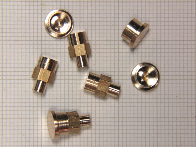
| Having
looked on web for the possible replacements, I've decided to make them,
just in case I cannot find suitable replacements.
Thus I ordered a tap & die set, and while waiting for arrival, I made a set of four. All that is left to do is cut the thread, and then drill a hole through the cup body, to allow oil to pass.
|
|
|
Thinking it over, I've decided that oil cups and caps need not at all be threaded, for they shall be
removed and placed back often during a working day, each time a drop of
the spindle oil is put into the
cup.
And as a final touch, in order to prevent caps from falling off accidentally, I have added a tiny O-ring to the cup body. This way, cap will stay in its place, and yet, be easily taken off, as well as placed back. |
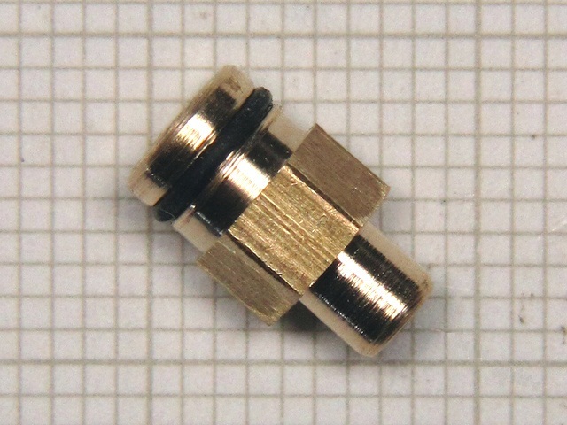 |
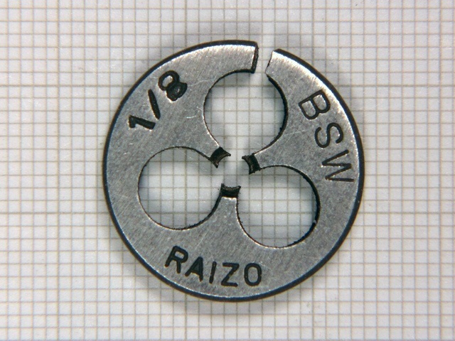
| Having
received 1/8" BSW die, it was now easy to cut tread, and thus finish
all of the headstock oiler caps.
Now finished, and ready to be mounted, shown in second image. |
 |
| Finished
and mounted in place on headstock bearings.
If I manage to procure the original oil caps, then it will be easy to replace them. |
 |
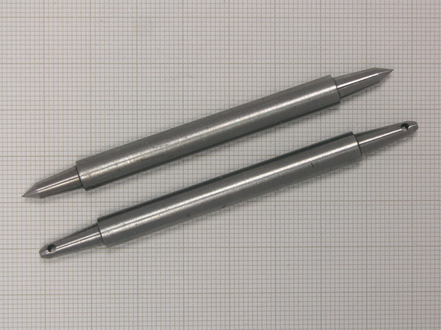
| The
important part of the tailstock for turning between centres are the
centres.
Out of three types offered by Lorch here are two, double ended, male and safety female tailstock centres. Each side carefully ground to shape in factory. |
 |
| Another
important part is the tailstock runner with ejector
pin.
It can hold any of the large number of tapered inserts, like drill bit holders, male or female centres as well as the special boring or milling bits. As supplied by Lorch a typical set is shown in the second image. |
 |
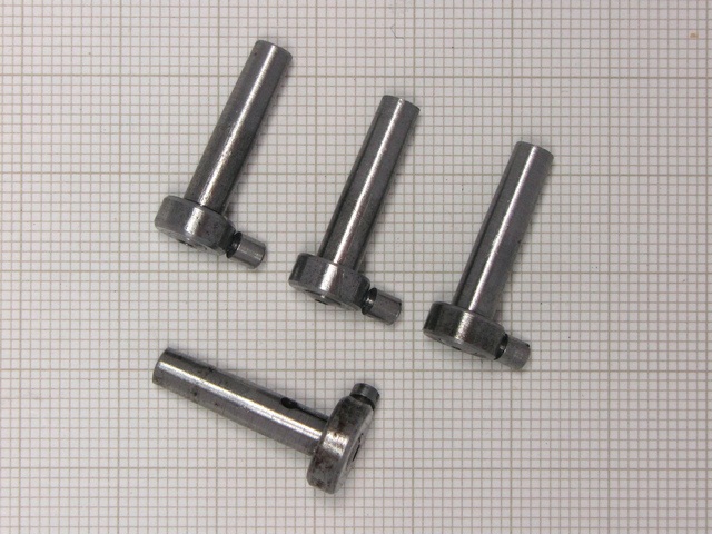
| Having
a sample of a drill bit holder, it was an easy task of making a set.
I have modified the original design slightly, then I made a set of three, for drill bits with shank of 1.0 mm, 1.5 mm and 2.0 mm. Thus I covered requirement of most drill bit sizes needed in watchmaking. Modification was nothing else but use of an older, proven, method of holding drill bits, rather than using split collet type as used by Lorch, details are shown in the second image. |
 |
| Practically all of the lathe tools, like centres, milling bits and drill bit holders are always attached to their corresponding carriers by use of taper. | 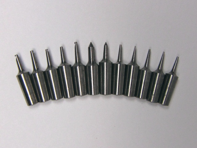 |
| It
is worth mentioning that the taper used on all of the accessories for
watchmakers' lathes, by Lorch, is always 1:25, the included taper angle is
2� 17' 32.79".
The accessory size does not matter and it does not, by any means, necessitate the change of the taper. Apparently, the same taper angle has quite satisfactory holding properties for small, as well as for large tool bits.
|
 |
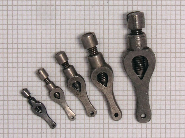
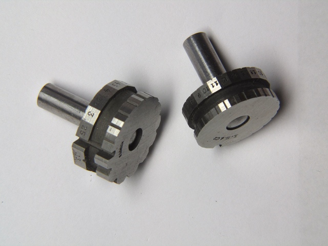
| For
turning between centres, i.e. 'dead centre turning' it is important to
have a set of the lathe dogs, to provide means of holding the piece to
enable turning it between the two centres.
Here is a smaller set of five lathe dogs Nr. 1 - 5, although the original set as was usually supplied by Lorch contained either 8 or 10 pieces. |
 |
| Of
course, for much smaller pieces, like balance staffs, one would have used ferrule,
They came in a variety of sizes and forms, they were procured either through material houses, or were shop made by a watchmaker. Ferrules are normally driven by a bow and string, so most of them have a tiny groove in the body to accommodate string. |
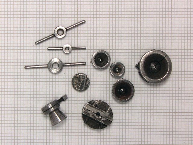 |
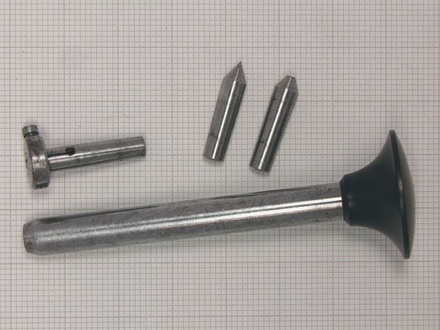
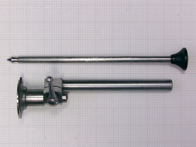
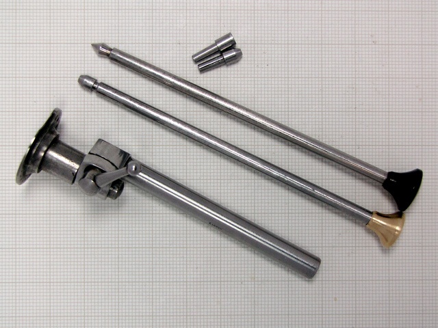
| Here
as another accessory that has few parts missing, the universal pivoting
runner.
In the second image are shown all the components, the missing is a drill holding runner and the two drill bit holding inserts. I shall be making these parts as the drill holding runner is the same diameter 4.0 mm as the centring runner. I'll try to find the exact sizes of original drill bit holding inserts so that I can use the original ones if I ever manage to buy them. |
 |
| With
help provided by a chap from UK, I got all relevant dimensions and went to
work.
With the cross slide set in the correct position for turning taper, I made three blanks, and then drilled one to fit the 1.0 mm drill bit shank. It worked fine after slotting, so I drilled another one to fit drill bit shank of 1.5 mm. Essentially I need only two sizes since almost all of drill bits from 0.08 to 1.5 mm, found in my tool arsenal, are with shank diameter 1.0 mm and 1.5 mm. |
 |
| Drawing
to the right shows the principle of use of the tool described above.
Re-pivoting would would be very hard to achieve with any accuracy without such a tool. It allows accurate centring and drilling when replacing a broken or badly worn pivot. Normally a tool set consists of several centring plates, as shown in second image, which are allowing replacing pivots from the very small to clock sized, permitting centring of pinions as large as 1/4" i.e. 6.35 mm in diameter. |
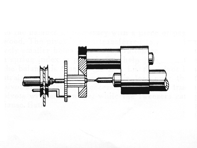 |
| Typical use of the tailstock attachment for re-pivoting. | 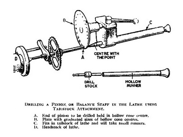 |
| Another
very important use of the No. 10 Universal tailstock runner is to hold the
Jacot drum serving as a support for the process of burnishing clock and
watch pivots.
The clock arbours are way too long to fit in Jacot lathe that is intended only for use with wrist and pocket watch arbours. Lorch, Schmidt & Co. made two Jacot drums for use in a lathe, one to fit pivots 1/100 mm to 25/100 in steps of 1/100 mm, and the other to fit pivots 0.30 mm to 1.40 mm. |
 |
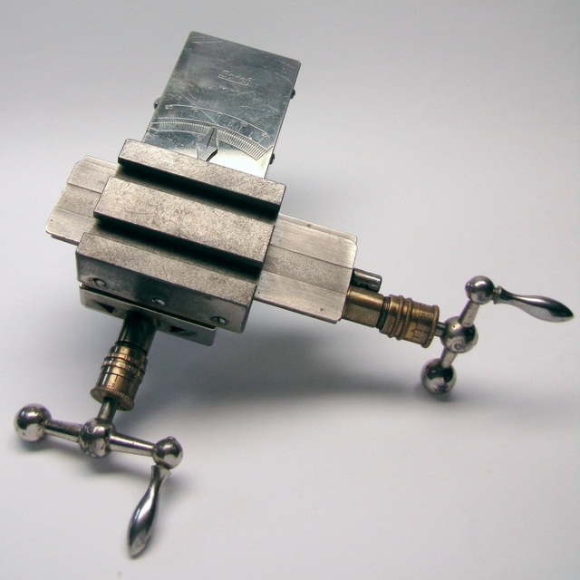
| For
turning some parts for watches it is preferred to use Cross Slide i.e. the
Compound Slide, using the tool post to firmly and accurately hold the
cutter.
Thus, it is easily possible to quickly turn parts to length and diameter accuracy of 1/100 mm, repeatable at will. Longitudinal and transverse travel of the cross slide are both 55.0 mm. This allows a lot of turning possibilities as compared to T-rest turning with a graver, which is mainly suitable for turning staffs and similarly small parts. Some watchmakers prefer to turn staffs using cross slide mounted cutting tool. |
 |
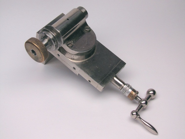
| Another
quite indispensable tool is the Milling/Drilling attachment mounted on the
vertical slide.
With vertical movement one gets third axis, applicable in many lathe operations. One of the now possible lathe operations is making wheels for watches with a division plate mounted onto the back of the headstock, and wheel cutter mounted on an arbour held in the quill driven by the overhead drive pulley. Vertical travel of the quill, as referenced to the lathe centreline, is 8.0 mm below, and 35.0 mm above. |
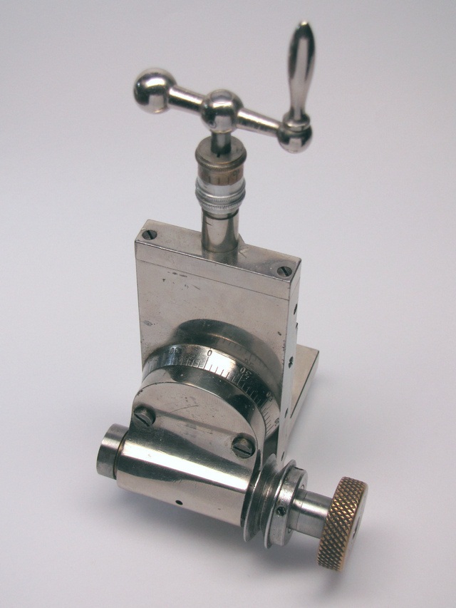 |
| Couple
of additional images of the vertical slide with the Drilling/Milling
attachment showing the graduated disc for setting the angle.
The quill can be rotated full 360 degrees, by releasing the two screws, then set and fastened to any required angle. Second image shows the mounting plate used to attach the vertical slide to the top surface of a cross slide. |
 |
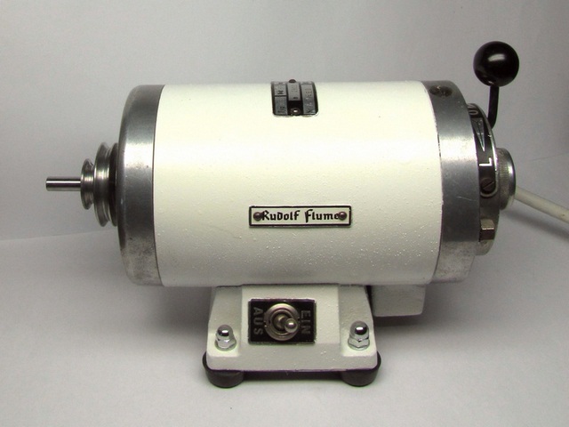
| The
Multifix, RE60 induction repulsion motor, capable of running in
either direction, having both, speed as well as direction of rotation lever
controlled.
Practically constant torque across the whole speed range from 4800-0-4800 RPM. Continuos duty rated power 60 W, (1/12 hp) powered from 110/220 V AC mains. Quite suitable for driving a D-bed watchmaker's lathe. |
 |
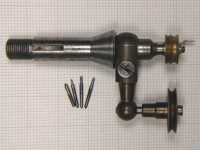
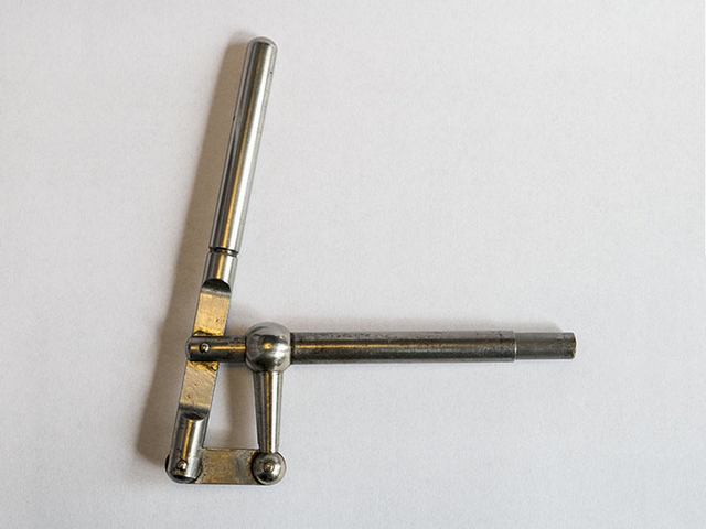
| Nr.
40 Hebelbohrvorrichtung
A lever operated device, used mounted in the tailstock for both drilling and milling. It accepts all of the standard tapered inserts.
|
 |
|
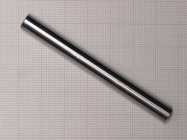
I picked a rod of ground silver steel, which I drilled through in my
instrument lathe to a diameter of 4.4 mm, then reamed it to the wanted
size of 4.5 mm with a calibrated reamer.
In the next step I placed it between centres in the lathe and turned close to 7 mm. Then, using the cross slide grinder, I simply ground the surface to exactly 7.00 mm. Done it this way to achieve the concentricity of the two surfaces as close as possible to one axis, with tolerance better than 5 micrometers. |
 |
| After
finishing the tailstock runner I placed it in the tailstock and razor
blade tested it, with a very good result as can be seen in the photo to
the right.
This newly made accessory shall serve it purpose very well, until I can procure the replacement as has been a part of the set originally. |
 |
| My
attempt to find original lathe box has taken too long without producing
result, so I have decided to make the box myself.
Instead, I've managed to find and purchase a new and empty pinewood box that only needed making inner fittings to house the lathe and accessories. The job was easy after making plan of placing all of the lathe parts in it. The second image shows the result of careful planning and execution. |
|
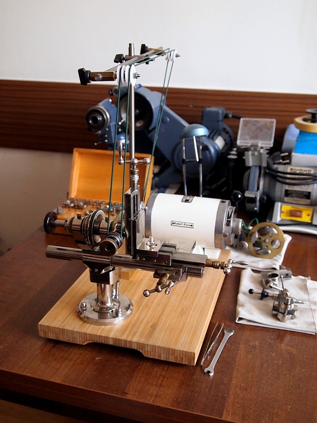
| The
next step was to provide base for lathe and the motor. I've decided to use
laminated bamboo kitchen cutting board.
When that was done it was necessary to provide the belt tensioning device. I've extended the post of the belt tensioning device to be used to carry the overhead drive for milling and drilling attachment. Belt transmission pulleys were all made out of Delrin, each having a ball bearing press fitted into its body. Motor pulley was fitted with a new steel pulley, instead of the aluminium one, which has shown traces of wear. The lathe driving belt is 3 mm in diameter, textured Polycord and the overhead drive belt is 2 mm in diameter, also the length of textured Polycord belting material. |
 |
|
In order to provide means of sharpening Tungsten Carbide Gravers for turning
parts and use the Levin TC graver sharpening kit, a new mounting shoe was
needed.
Levin kit was initially designed to fit a WW style bed, thus a new mounting shoe had to be made. Following a Levin design I've made a new one out of a short piece of duralumin with a slot on a bottom side to fit Lorch. Shown at the second image. |
 |
| Shown on the image to the right, Levin device mounted securely on the Lorch bed, already in use. | 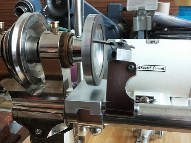 |
| Work continues... |  |
|
|
|
|
Copyright � 2004, 2011, 2014, 2015, 2016, 2020 by Dushan Grujich. All rights reserved. |
|
|
|
|