CHAPTER I
Our project consists of planning and designing a
multi-storied residential building. This involves thorough consideration of
various architectural and structural aspects. We have tried our level best to
keep in mind these aspects and have proposed a plan for residential building.
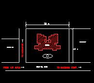
The building is a STILT + 7 storied
building and is proposed at Nizampur, BHIWANDI. The SITE
PLAN for the same is attached in our synopses.
The various architectural and structural drawings are normally hand drafted. This is a tedious job and is now widely being replaced by computerized drafting using computer packages. This method of drafting is very quick and gives almost 100 percent accuracy except for some mistake of ours. There are various predefined specifications which make the work much more easier. Also various architectural aspects of beautification and colour schemes are by default there by making the work complete in every aspect.
The structural analysis or designing of simple or complex structures is done manually by a structural designer or a RCC Consultant. This involves consideration of all factors, which affect the structure in one way or the other. These factors depends on the
site conditions on which the structure
is to be built, the climatic conditions of the area, the loads that the
structure will be subjected to, wind effect, the seismic forces (for high rise
structures) and various other aspects of designing. This is also a very tedious
job and any manual mistake can create a hazardous situation.
To improve or crosscheck the design of structure
computer packages are widely employed all over the world. These applications
make the work much simpler and the designed structure is economical and
structurally stable if the data entry is as per specifications for various
conditions. Incorrect data entry may give erroneous results, which may impose
great problems. Hence, care should be taken to avoid hazardous situations.
In our project we have used the following computer packages to plan, draft and design the given multi-storied residential building.
1. PLANNING
keeping in view the building bylaws and aesthetics
2. DRAFTING
of the working drawings by using AutoCAD-R14
3. DESIGNING
the given structure by STRUT
The COMPUTER
TOOLS used by us are the latest versions and are widely used all over the
world
CHAPTER II
Planning is an important part of the execution of any construction activity. This job involves the perception of mind in imaging the form, shape and size of the proposed work. The making of drawings, designs, estimates, pictures, models etc. are all the responsibilities of an architect or designer. And only after these things are completed, the actual construction work start.
It is the architect or designer who decide about
the outer figure and inner lay out of the proposed work. So far this reason, the
designer has to keep each and every point in mind before star in the planing of
the proposed work. In our project,
the design is based on the following:
(1) FUNCTIONAL PLANING
The
principal of functional planing forms the backbone of any work. It aims at best
utilization of spaces and other resources available. The proposed building has
been designed in such away to fulfill its basics function for which it is to be
constructed.
(2) PRINCIPALS OF STRENGTH
It
aims at safe and strong construction resulting in safety and feasibility. The principal of structural planing has been fully kept in
mind in designing this project. The R.C.C. has been specified for load bearing
portions.
(3)
ESSENTIAL SERVICES
The essential services, which have been provided in this residential building, are electrical fitting, sanitary fittings, water supply fitting, staircases, lifts and circulation space. Other amenities like garden space, swimming pool and recreation club is also proposed.
(4) BEAUTY
Principal
of constructing beautiful and pleasing building which in architecture known as
Aesthetics. The Aesthetics is very important in designing of building. There is
around 22 composition of aesthetics. Not all, but some of them have been kept in
mind in giving beauty to this project.
(5)
COST CONSIDERATION
The
other very important principal of Architecture is economical planing of the
proposed building. But in our project this principal is of not much importance
because the project has no cost limitation though we have still tried to provide
economical planing of the proposed building. These above are the basic
principals, which have been kept in mind while planing.
The
other aspects, which we have been kept in mind, are as follows:
1.
ORIENTATION
Every
building has to be designed so that it is safe from climatic hazards of sun,
wind and rains. Out of this elements sun is most important which alone can
create great difference in the climate of any area, and livability and
comfortabilty. Hence building shall be designed in such away that it is safe
from hot summer sun while winter sun is always preferable in hot climate as that
of India. Almost some parts of the
building are used exclusively at night and others in day or for occasional
needs. So parts of the building,
which are to be used at night, should be cool at night and parts of the
building, which are used at day, shall be well lighted. This we can achieve by
proper orientation of building. Orientation is called the east direction i.e.
the direction of the sunrise. So the building shall be design to the direction
of sunrise, sunset and vertical angles of sun during various month of the year.
This is called orientation or we can say that placement of building according to
sun direction is called orientation.
1.
To make the climate comfortable through out the year.
2.
To cut off the summer sun outs and let the winter sun inters in summer.
3.
To make the building ventilated properly by considering prevailing wind
direction
4.
Some times building has to be oriented towards some beautiful natural
scene.
1.
Mark north direction of the map.
2. Mark the important prevailing wind
directions on the map for the part of the year on which orientation has to be
given priority.
3. Marked the
beautiful scenery at site or mark the direction of any important natural
scenery.
4.
Mark
the set back (front, rear and side
set backs) according
to applicable bylaws.
5.
Place the building in such a way that:
(a) Parts of the
building which are used in day times shall be placed towards south direction.
(b) Parts of the
building which are used in night shall be placed for cooling effect towards
north or east.
(c) Kitchen shall
be placed towards North direction.
(d) Toilets, stores
and staircase can be placed towards west direction.
(e)
Bedrooms shall receive air during night.
(f)
Drawing room, dining room and kitchen shall receive air during day.
(g) Kitchen and
toilet shall not be placed in such a way that foul air comes towards drawing and
dining area. Building shall be so placed that it faces the roadside.
6.
Windows shall open towards the side of good view specially those of
drawing, dining room and lounge.
2.
LANDSCAPING
The aims, which are not fulfilled by the method of orientation, are mostly achieved through landscape architecture. Landscaping is an art of lying out of gardens/parks etc. with respect to the building. It is also an important principal of architecture. The trees should be planted on the sun sides to avoid the rays of the sun. The shrubs could be used for screening the objectionable views and forming the desirable ones. The other elements of landscaping are sculptures, fountains, water bodies and natural timber logs or stones etc. All these elements have been utilized up to the extent in designing of working.
If the sunrays are still are
unavoidable, then the artificial sun shading is adopted such as sunshades,
louvers, chajjas etc. These artificial elements are very important because it is
not possible to provide trees, shrubs etc. on every side of the building. So
these elements have also been provided according to the needs of the building.
All these principals and aspects have
been kept in mind to achieve the proposed target. The building has been designed
in the light of these principals and aspects. However, some might have not been
covered due to reason beyond our thinking.
3.
CLIMATE
Climate
is the combined effect of the temperature, rainfall and wind. The sun's path
from East to West changes from the Tropic of Capricorn (23 1/2 degree S) towards
the equator and then towards the Tropic of Cancer (23 1/2 degree N) and back to
the Tropic of Capricorn in one year. Hence it will be seen that the altitude of
sun is the highest in tropics and decreases beyond the Tropic of Cancer and the
Tropics of Capricorn. The total heat absorbed depends on the intensity and
duration of the exposure of the earth surface to the rays of the sun.
India is a basically tropical country
between latitudes 7 - 30 degrees. From North to South the climate goes on
changing continuously. The design of the building also changes accordingly. In
India the burning sun rises and set like a clock, dividing the day in to equal
parts of lightness and darkness. The sun also controls the distribution of the
rain. Hence, the buildings need protection from heat. Wind effect and seismic
analysis should be also considered for design of buildings.
4.
SITE SELECTION OF BUILDING
A well designed building, however beautiful and comfortable, may turn in to a bad place of living if it does not have a good surrounding environment, e.g. if a building is located by the side of a filthy and low laying area, their will be difficulty in approach, and the residents will have to face the bad climatic conditions and natural hazards. It is a dangerous and an unwell comes place. Site has great influence in the selection of plots of any building of cost of land is usually controlled by its locations.
Following are major considerations for
site selection for a building:
(a)
Physical Consideration:
1.
The land must be fit for use for any type of building.
2.
It should not be low laying area to avoid flood during rainy season.
3.
Soil Condition should be safe for the building.
4.
It should be safe from earthquakes.
(b)
Health Consideration:
1. Surrounding
environment should be neat and clean, safe from every type of pollution.
2.
Water should be drinkable, safe and soft. It should be safe from and
natural and climatic hazards and from dangerous animal and insects.
(c) Aesthetics Consideration:
1.
Site should have a beautiful environment.
2.
Proper green areas and easy plantation should be possible.
(d) Good transportation facilities:
1. Site should be
well connected and easily approachable.
2.
Site should be close to Bus stand and Railway station etc.
3.
Site should be such located that it is convenient to reach the place of
work.
(e) Economic and cost consideration:
1.
Cost of land should be low.
2.
Cost of development should be low.
3.
There should be no legal hazards.
4.
The site should be suitable for use according to master plan.
5.
Construction material and labor should be easily available.
(f) Community facilities and Utility:
1.
Educational, medical facilities, small shopping center, police station,
playground etc. should be available close to the site.
2.
Site should be well developed and should have good water supply system,
sewerage system, and well electrification etc.
CHAPTER-III
PLANNING OF FLATS
PLANNING:
Flats are today design in such variety that it is
impossible to devide them into hard and fast categories. Some characteristic
(e.g. of frontage or number of stories) has such a strong influence or internal
planning that some generalization can be made.
FLATS:
The flat is primarily a type of dwelling for urban
development for crowded areas and expensive sides. Its use enables more people
to like in towns and they’re for close to center of work and entertainment
with corresponding avoidance of loss of time in travelling from suburban houses.
Flats can be planned as low rise with heights up to three stories. For flats
above this height lifts are necessary, unless the levels of the site allow an
entrance at a level other than ground level.
A criticism frequently leveled against flats is a
possible lack of privacy but it is doubt full if this lack is grater then in
ordinary town houses, planned in terraces, for each flats can self contained and
approached from a staircase and lift hall which are infect a vertical extension
of the street. High rise building generally cast more than low rise, largely
owing to the high cast of vertical circulation.
Four type of access can be considered as follows.
(a) Balcony (or gallery) access: This access type is suitable for
either flats or moistens but balconies tend to be noisy, exposed to the weather,
potentially dangerous for young children and can induce giddiness in some
occupants. With moistens balconies occur only at alternate floors and over
shadowing of the floor below is reduced. One advantage of this type of access is
the encouragement it gives to social contact.
(b) Access from the cross-centilated lobby or small semi-private balcony
open to the air: This has developed from the acceptance of one common
staircase in high buildings with entrances to individual flats in the
cross-ventilated lobby. It provides a good degree of privacy but the
cross-ventilated lobby is draughty.
(c) Internal Lobby Access: This is suitable for flats and comprises
an internal lobby served by lifts and an adjoining wide.
DATA:
For
local authority work all plans must now show the furniture drawn on and should
be designed to accommodate furniture as set out below.
Kitchen. Small tables unless one is
built-in.
Meal space. Dinning table and chairs.
Living areas. Two or three easy
chairs, settee, TV set, small table, reasonable quantities of other possessions,
such as radiogram, bookcase.
Single bedrooms. Bed or divan (2000mm
x 900mm); bedside table; chest of drawers; wardrobe space for cupboard to be
built-in.
Main bedrooms. Double bed (2000 by
1500) or alternatively two single beds each 2000mm x 900mm; bedside table; chest
of drawers; double wardrobe or space for cupboard to be built-in.
Other double bedrooms. Two single beds
2000mm x 900mm; bedside tables; chest of drawers; double wardrobe or space for
cupboard to be built-in; small dressing table.
Where bedrooms are designed as study/bedrooms or
bed sitting rooms, space must also be provided for such additional furniture as
tables, desk and easy chairs. The scale of provisions depends on the nature of
the activity and the age of the occupant.
Requirements
for the provision of the electric socket are generally the same for local
authority housing and for that built to correspond with the requirements of the
National House Builders Registration Council as follows:
Working area of kitchen
4
Dining area (local authority)
1
Dining area (private)
2
Living area
3
Bedroom
2
Hall or landing
1
Bed-sitting room in family dwellings
3
Bed-sitting room in one person
dwellings
5
Integral or attached garage
1
Walk-in general store (in house only)
1
Any
sockets required for night store space or water heating are in addition to the
above.
The
sale of accommodation to be provided is sometimes governed by statutory
requirements, as in the case of local authority housing or, in the private
sector by the Technical Requirements of the National House Builders Registration
Council.
For convenience this accommodation can
be listed under the following headings:
Food
preparation/ laundry
Refuse
disposal
Eating
Leisure
Sleeping
Personal
care
A
kitchen plan is a complex problem. It is the workshop in which the housewife
performs many operations of widely differing natures. Good and expensive
equipment in it self does not guarantee a solution, for unless the equipment is
properly arranged and the space planned as a whole, labor and effort is not
reduced. It is the relationship with equipment to use and the sequence of
operation that is the important factors.
The sequence of operation in
connection with meal preparation is:
1. Delivery or collection of goods
together with storage.
2. Preparation of food.
3. Cooking.
4. Preparation of the dining table.
5. Distribution of food to the table.
6. Return of food and crockery from
the table.
7. Washing up.
8. Putting away of washed up crockery,
glass and cutlery.
Item
1 involves the ladder, store cupboards, refrigerator and freezer. In flats the
ladder is often omitted and there is rarely room for a large freezer. There is
however a tendency for housewives to buy food in bulk and provision for its
storage is becoming more necessary, both in the form of dry storage and freezer
accommodation.
Item
2 needs the use of workshop surface together with the sink and these must be
closely related to each other and to the ladder and cooker which is the major
feature of item 3. It is essential that proper workspace is provided at both
sides of the cooker.
Item
4 requires linen and tableware to be taken from storage to the table, partly by
way of the worktop or in the case of hot plates and dishes by way to the cooker.
This can not be completely separated from Item 5, which involves the conveyance
of food from cooker and worktop together with some food directly from storage to
the dining table.
Item
6 reverses the process of Item 4 and 5 so that surplus food is returned to
storage, dirty china and cutlery to the sink, clean china and cutlery together
with linen to storage.
Item
7 involves the sink or a dish washing machine. If this is to be provided,
consideration must be given to its plumbing.
The
collection and disposal of refuse of all types needs careful consideration,
particularly with the increasing amount of packaging for disposal. For
individual houses and small groups of flats the dustbin or sack remains the only
practical solution. The placing of the dustbin should be given proper attention
as part of the planning so that it is conveniently sited relative to the refuse
producing area (kitchens etc.) and to the access for the refuse collection
vehicles.
With
larger block of flats, chutes are normally installed usually in one of two
forms:
(a) Separate chutes from each flat to
individual dustbin at ground level and,
(b) Chutes serving a number of flats
and delivering to a main container at ground or basement level.
The second type is more common and
usually has hoppers at all floors. The room to accommodate these containers can
often be grouped with stores but the weight and size of the containers makes it
necessary for the collector's vehicle to obtain easy access.
The chutes must be planned conveniently for the
flat and preferably in its own open lobby with adequate natural ventilation. For
reasons of economy a single chute can be planned to serve a number of flats at
each floor level. With large-scale developments it may be possible to
incorporate incineration or a water-borne system of waste disposal.
The activity can, in the flats takes place either
in the leisure area or be associated with food preparation. It is preferable, if
possible, for a separate area to be provided particularly so that it may then be
used for other purpose children's homework, sewing, etc.
It is essential that eating area be closely related
to the food preparation area with direct access by door for the serving of meals
and subsequent clearing away. A serving hatch can be provided but it should have
shelf space on both sides.
Leisure
activities in the home include those, which are normally carried out with the
family, such as watching TV, and other activities, which required quieter
condition (e.g. playing chess). Activities may also include those, which, in
them, are noisy, (e.g. listening to pop-records); these are best carried out
away from main leisure areas.
It is important, therefore, that room set aside for
leisure is flexible and can provide for different arrangement furniture to suit
changing activities. The room should be large enough to accommodate comfortably
all the occupants, or in the case of young families, the eventual number of
occupants of the house.
The room must provide sufficient space for two or
three easy chairs, a settee, and a TV set, a small table, a reasonable quantity
of other possessions such as a radiogram and bookcase. With the gradual
disappearance of the open fire, more formal arrangements of the furniture are
less necessary and the design of the room should allow for flexibility in the
layout
Economics
of internal planning and space saving are gained by the reduction of corridor
and connecting spaces to a reasonable minimum but excessive elimination
generally reduces privacy and comfort. It is important however that the widths
of circulation spaces should not be reduced so that they are inconvenient for
people to pass each other. particularly in public areas such as lobbies and
common stairs which can be intensively used at peak hours. It is also necessary
for circulation areas to be properly lit both naturally and artificially. Doors,
particularly to cupboards, should not obstruct circulation space when open.
In addition to circulation within the flat,
consideration must also be given to entering and leaving and to every thing that
happen in the immediate vicinity of the home, such as putting out washing,
fetching fuel (if stored externally) etc.
Flats should have storage comparable to that in a
house. Four or more person requires 1.4m2 of general storage within the flat.
There should be a separate store elsewhere of 2.0m2 for each flat whatever size
of family. If the flat has a garden, additional storage is required for garden
tools.
Bedrooms should be provided so that each member of
the family other than the parents can have a single bedroom to him/herself. This
need not apply to very young children. Bedrooms should have direct access from
landing or corridor or should no circumstances be inter- communicating.
Double bedrooms should be planned to accommodate
two
Single beds and the parent’s bedroom
should be large enough for a cot occasionally. Chlordane’s bedrooms can
sometimes be planned to accommodate bunk beds thus releasing some of the floor
area for other furniture such as tables and easy chairs.
Most bedrooms should be provided with built-in
cupboards allowing not less than 600mm run of hanging space per person.
Cupboards should be atlas 550mm deep internally and doors 2000mm high with extra
cupboards above reaching to the ceiling for the storage of the less frequently
required articles.
CHAPTER - IV
The conventional methods of preparations of working drawings involve tedious calculations and accurate measurement during drafting. Professional draftsmen are to be employed and larger working area has to be provided. The instruments used are also bulky and cleanliness during drafting has to be maintained. Using AutoCAD software can very well eliminate this difficulty.
In AutoCAD the working drawings to be drafted can
be done either graphically or by giving commands on the command line. After
drafting the various working drawings, plots or printouts of the same can be
obtained using the print command. The drafted drawings can also be saved and be
edited as and when required.
This introduction described the concept of electronic drafting and the capabilities of Auto CAD (Rel. 14). Also included is an introduction to Auto CAD terminology and documentation.
This section describes the main component of the
Auto Cad interface and explains how to enter command and how to find help.
We use AutoCAD by running commands using one of
these of methods:
Ø
Choosing a menu item
Ø
Clicking the tool on tool bar
Ø
Entering a command
We can get help about a command or procedure by
selecting AutoCAD help topics from help menu. We can also get help about the
current command, or tool by using one of these contexts- sensitive methods:
Ø For a command, enter help for F1 while a command is active.
For
a dialog box, choose the dialog box help button or press F1.
Ø
For
a menu, highlight the menu item and then press F1.
When we start an AutoCAD it creates a new unnamed
drawing. We can either start drawing objects in this blank drawing or open an
existing drawing.
If we open an existing drawing all of the commands
and system variables settings last used on that drawings are restored
Because this information is saved in
the drawing file.
When we start a new drawing there are a few setting
we will want to establish to assist us during the drawing process.
Units
determine the measuring unit we will use to draw objects, feet and inches, mm
and so on.
Scale determines the size of a unit when plotted on paper. In
AutoCAD we draw every thing in full scale in the unit we setup so we don't have
to worry about scale unit we are ready to plot a drawing.
To help us visualize units, we can display an array of dots called a Grid
on screen. The grid helps us to visualize the size of units on our screen if we
increase or decrease the magnification of our drawing.
Limits indicates to AutoCAD where in the drawing areas infinite
spaces you intend to draw AutoCAD display the grid only within these limits also
controls some viewing options.
Snap enabl
To help us to draw a variety of geometrical shapes
AutoCAD has commands that cruets many different types of objects. We are able to
draw lines, multi--lines, circles, donuts, arcs, ellipses, points, rectangles,
polygons, splints etc. In addition to these simple geometric AutoCAD provides
the capabilities for creating more example objects like polyamines with varying
width, ANSI hatch patterns, solid fill hatches for architectural details.
AutoCAD has several text creation and editing
commands. Text can be created as single line or as a paragraph. We can control
the text style, font, size, angle and properties. We can attach visible or
invisible text to objects that describes the object. Such text is known as an
attribute and can later be extracted into a list or reports.
AutoCAD
has extensive dimensioning leader and tolerance capabilities. We can control
every aspect of a dimension's appearances and behavior.
In addition to grid and snap, AutoCAD has many
tools that you can use to locates points and create objects accurately.
One method is to specify coordinates. All drawings
are super imposed on an invisible grid, or a coordinate system, with a
horizontal X-axis or a vertical Y-axis. A single unit in a coordinate system
represents the unit that you choose to use for drawing (an inch, millimeter,
kilometer and so on). You can establish grid and snap settings that match the
units of the coordinate system or are some multiple or fraction of it.
There are certain properties that are associated
with all objects that you create in AutoCAD.
The style of the line, or line type, that an object
is drawn in can be set to many different styles, such as solid, phantom, center,
dotted or hidden. You can create your own dashed lines or more complex
line-types such as center line type, batting linetype, dashed linetype and hot
water supply linetype.
Most engineering and architectural drawings contain
repetitive symbols. In AutoCAD, you create such symbols by combining several
objects together into a single object called a block. The block can be inserted
in to your drawing many times as a standard symbol. If you change the master
block definition, all instances of the block, references are automatically
updated (unless you have modified a block reference in some way).
In a block definition can be saved either with the
current drawing or as a separate drawing file. If you want to insert the block
into other drawing, you need to save the block as separate drawing.
Once you have create objects in your drawing, you
can use AutoCAD's editing and viewing tools to modify objects and display your
drawing in various ways.
After you create objects in your drawing, you will
usually need to modify your drawing in some way. AutoCAD provides a variety of
editing tools that minimizes the time it takes to make corrections.
Often, you may need to move an object to another
location, align it with other objects, or change its rotation. The MOVE, ALIGN
and ROTATE commands provide this capability.
If
you need to duplicate the object in drawing there are several ways to accomplish
this. You can also duplicate object and place copies at multiple locations.
If you decide an object must be longer in one
direction, you may use the STRETCH command. Another form of stretching can be
done on lines by using TRIM or EXTEND command. You can also move, copy, mirror,
stretch and rotate objects in a single operation using GRIPS.
Your AutoCAD drawing contains many types of data
that you can look up. You can list the properties of an existing object, like
its color, layer or linetype, and you can copy those properties and apply them
to other objects using the match properties command. You can calculate an area
that you define or that is enclosed by an object.
AutoCAD is also a three dimensioning modeling tool,
3D coordinates can be specified be entering their X, Y and Z components.
Spherical and cylindrical coordinates system can be used in addition to the
relative and polar coordinates mentioned earlier. The UCS can be positioned
anywhere in 3D space.
You can raster files in your AutoCAD drawing as
unique object types. Raster images can be copied, moved, rotated, resized and
clipped. You can also adjust the image color, contrast, brightness, transparency
and more.
AutoCAD supports query language so you can link
objects in your drawing to information in an external database created with
applications such ass dBase-III, Informix, oracle or paradox. With AutoCAD SQL
environment (ASE) commands, you can link data to objects, execute database
queries, create new database files and generate reports.
CHAPTER - V
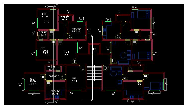
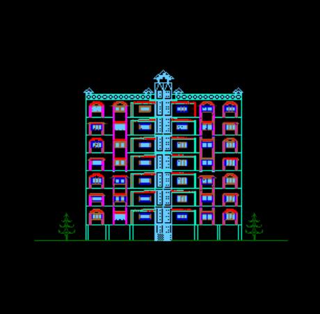
Following drawings which were drafted by us using AutoCAD- R14 are attached herewith.
2.
GROUND FLOOR PL
4.
SECTION
X-Y
5.
SECTION
A-B
7.
3-D VIEW
CHAPTER
- VI
STRUCTURAL
PLANNING
The development in the analysis of structure stress the need for close contact between the architect, how has a creative vision and structural engineer, who has an insight in the analysis of structures. This allows us to take maximum advantage of development in the structural analysis for erecting sound, economical and elegant structure with aesthetic beauty and functional utility.
THE
DESIGN PROCESS
Structural design is an art and science of designing, with economy and
elegance, a safe, serviceable, and a durable structure.
The entire process of structural planning
and design requires not only imagination
and conceptual thinking
(which form art of designing) but
also sound knowledge of science of structural engineering besides knowledge of
practical aspects, such as relevant design
codes and byelaws, backed up by ample experience, in tuition and judgment.
The
process of design commences with planning of structure, primarily to meet
the functional requirements of the user or the client. The requirements proposed
by the client may not be well defined. They may be vague and may also be
impracticable because he is not aware of the various implications involved in
the process of planning and design, and about the limitations and intricacies of
structural science. The functional requirements and the aspect of aesthetics are
looked into normally by an architect while the aspect of safety, serviceability,
durability and economy of the structure for its intended use over the life span
of structure are attended to by the structural designer. Many times, a
structural engineer is required to act in capacities of both - the architect and
the structural designer.
The
process of structural design involves the following stages.
1.
Structural Planning.
2.
Estimation of Loads.
3.
Analysis of Structure.
4.
Member Design.
5.
Drawing,
Detailing and Preparation of Schedules.
6.
Steps
followed in designing through struds.
1.
STRUCTURAL PLANNING
This involves determination of the form of the structure, the material
for the same, the structural system, the layout of its components, the method of
analysis and the philosophy of structural design.
For
example, if a large area is to be provided with a cover, the designer is
required to decide first the appropriate form and/or system of the covering
(roof) structure. He has to fix up whether the roof shall consist of steel roof
trusses and girders, or R.C folder plates, or R.C. shell or a cable-stayed
tension structure or a beam-slab grid system, or a pre-stressed hanging roof, or
combination of above. The form and the system will have to be decided from the
considerations of functional requirements such as unobstructed area, head-room
and also from consideration of economy and aesthetics. After deciding the form
and the system, the designer is required to select material appropriate to the
form. Of course, the choice of the material will also be governed by the
requirements of aesthetics, economy and the availability of the material. Once
the form and the material to be used are finalized, the layout of the component
members (e.g. positioning of columns, spacing of trusses, or beams,
configuration of trusses etc.) will be required to determined. And finally, the
designer will have to choose the realistic design philosophy and the method of
analysis appropriate to the structural system and the material used.
The
principal elements of a R.C. building are as follows:
*
Slabs to cover large area,
*
Beams to support slabs and walls,
*
Columns to support beams and
*
Footings to distribute concentrated column loads over a large
area of the
supporting soil.
After getting an architectural plan of the building, the structural
planning of the building frame is done. This involves determination of the
following :
(a)
Column positions
(b)
Beam locations
(c)
Spanning of slabs
(d)
Layout and planning of stair
(e)
Type of footing.
(a)
Positioning of Columns :
Following are the some of the guiding principles which helps in deciding
the column positions.
(1)
Columns should preferably be located at or near the corners of a building, and
at the intersections of walls, because basically the function of column is to
support beams which are normally placed under the wall to support them. There
can, however, be an exception in case of columns in walls on the property line.
Since column footing requires certain area beyond the column, difficulties are
encountered in providing footing for such columns.
In
such cases, the column may be shifted inside along a cross wall to make room for
accommodating the footing within the property line. Brackets may be taken out
from the column in continuation of cross beams to support walls along the
boundary line. Alternatively, a combined footing
or a strap footing may be provided.
(2)
When the center to center distance between the intersections of walls is large
or where there are no cross walls, the spacing between two column sis governed
by limitations on spans of supported beams, because spacing of columns decides
the span of the beam. As the span (and the length) of the beam increases, the
required depth of the beam and hence its self weight, and the total load on the
beam increases. It is well known that the moment governing the beam design
varies with square of the span and directly with the load. Hence, with the
increase in span, there is considerable increase in the size of the beam. On the
other hand, in the case of column, the increase in total load and hence the
increase in size due to in increase in length is negligible as long as the
column is short. Therefore, the cost of the beam per unit length increases
rapidly with the span as compared to beams on the basis of unit cost. Therefore,
larger spans of beams should preferably be avoided for economy reasons. In a
case, when two columns are provided, the beam becomes a three span beam length
of beam span reduced and it is required to carry only one concentrated load and
that too on central span which further reduces the moment in outer spans without
appreciable increase in design moment leading to considerable reduction in the
cost of beam. On the other hand since the cost of column is nearly proportional
to the load on it, increase in cost ( of columns and footings ) due to provision
of two columns (carrying half the load), over the cost of providing single
column will be comparatively less than the increase in the cost of beam due to
providing single column. Thus, the second alternative is likely to work out to
be cheaper. This is more true in case of multistory building
frames.
In
general, the maximum spaces of
beams carrying live loads up to 4 KN/sq.m. may be limited to the following
values.
Beam
Types
Cantilevers
Simply Supported
Fixed/Continuous
Rectangular 3 meters
6 meters
8 meters
The
upper limit shall be reduced by judgment for heavy loads (live load greater than
4 KN/sq.m)
(3)
Larger spans of beams shall also be avoided from the consideration of
controlling the deflection and cracking. It is well known that the deflection
varies directly with the cubes of the span and inversely with the cube of the
depth D(since the rigidity EI is a
function of bD3). However, for large spans, normally higher L/d ratio is taken
to restrict the depth from considerations of economy, headroom, aesthetics and
psychological effect (a long, heavy, deep beam create psychological feeling of a
crushing load leading to a fear of collapse) Consequently, increase in D is les
than increase in span which result in greater deflection for large span.
Therefore, spans of beams (and hence sp[acing of columns) which requires the
depth of beam greater than 1m should as far as possible be avoided.
(4) Column should be avoided inside a big hall as it mars the functional utility and the appearance, and obstructs the clear view and the useable space.
(5)
Larger spacing of columns not only increases the span and the cost of beams but
it increases the load on the column at each floor posing problem of stocky
columns in lower storey of a multistoried building. Heavy section lead to
offsets from walls and obstructs the floor area.
(6)
When the locations of two columns are very near (e.g. as it occurs when the
corner of a building and the point of intersection of walls come very close to
each other), then one column should be provided instead of two at such a
position so as to reduce beam moment.
Orientation
of Columns
Normally,
columns provided in a building are rectangular with width of column not less
than width of the supported beam for effective load transfer. As far as
possible, the width of column should also not exceed the thickness of the wall
to avoid offsets. Restriction on the width of column necessitates the other side
( the depth ) of column to be larger to get the desired load carrying capacity.
This leads to the problem to the orientation of such rectangular columns for
which the following lines should be useful.
(1)
According to the requirements of aesthetics and utility, projections of
columns outside the wall, in the room ( and especially at the corner ) should be
avoid as they not only give bad appearance but also obstruct the use of corners,
and create problems in placing furniture flush with the wall. The depth of the
column shall be in plane of the wall to avoid such offsets. The problem of
projection of column normally occurs in the internal walls since they are
usually thinner. Now a days 150mm thick block walls allowed by the construction
authorities for outer walls also to get more floor space, has posed this problem
for external walls too, because the width of column is required to be kept not
less than 225mm to prevent the
column from being slender. In such cases 150 mm thick columns may be provided
only at the intersection of two walls at right angles where 150 mm side of the
column could be matched with one of the walls. Such as column should be
laterally braced at the lintel
level by connecting the
column to lintel in the cross wall.
This will reduce the effective length of the column and keep the column
short. Beside, this solution is possible only for upper two floors since 150mm
thickness may become inadequate for the lower storey columns carrying heavier
loads. For this, only alternative
is either to use L shaped columns at the corners or T -shaped columns at the
intersection of intermediate cross walls. Alternatively, spacing of the columns
should be considerable reduce so that the load on column at each floor is less
and the necessity of large for columns does not arise.
(2)
When a column is rigidly connected to beams at right angles, it is
required to carry moment in addition to the axial load. In such cases, the
column should be so oriented that the depth of the column is perpendicular to
the major axis of bending so as to get larger moment resisting capacity. (i.e.
the depth of the column shall be in the plane of bending). It should be borne in
mind that increasing the depth in the plane of bending not only increases the
moment carrying capacity but also
increases its stiffness, thereby more moment its transferred
to the column. This can be avoided to some extend by limiting the depth of
the column but increasing its moment or resistance by increasing the percentage
of steel.
(3)
Also, when the effective length of the column in one plane is greater
than that in other plane at right angle (e.g. Leff of a column in a plane frame
free to away is more in the plane of the frame than a cross it when all frames
are laterally braced at the top), The greater dimension shall be in the plane (
of the frame) having larger effective length so as to reduce the governing leff/
D ratio and to increase the load carrying capacity of the column.
(b)
Positioning of Beams
Following are some of guiding principles for positioning of beams.
(1)
Beams shall, normally, be provided under the walls or below a heavy
concentrated load to avoid these loads directly coming on slabs. Basic principle
in deciding the layout of component members is that heavy loads should be
transferred to the foundation along
the shortest path.
(2)
Since beams are primarily provided to support slabs, its spacing shall be
decided by the maximum spans of slabs. Slab requires the maximum volume of
concrete to carry a given load ( i.e. its
volume/load ratio is very high compared to other components). Therefore, the
thickness of slab is required to be kept
minimum. The maximum practical
thickness for residential/office/public buildings is 200mm while the minimum
is 100 mm. The maximum and minimum spans of slabs which decide the
spacing of beams are governed by loading and limiting thickness given above.
In case of buildings, with live loads less than 5KN/sq.m. (i.e. other
than warehouses, godowns and heavy duty floors), the maximum spacing of beams
may be limited to the value of maximum spans of slabs given below.
Support
Cantilevers Simply
supported Fixed/continuous
condition
Slab
Type
1-Way 2-Way 1-Way
2-Way 1-Way
2-Way
Max.
Span
1.5 2.0
3.5 4.5
4.5 6.0
(in
mts.)
(c)
Spanning of slabs:
This decided by the position of supporting beams or wall. When the
supports are only on opposite sides or only in one direction, then the slab acts
as a one-way supported slab. When the slab is supported in two
perpendicular directions, it acts as two-way supported slab. However, the
two-way action of slab does not depend only on the manner in which it is
supported but also on the aspects ratio Ly/Lx ( the of long span Ly to Short
span Lx), the reinforcement in the two directions (Astx/Asty or Mux/Muy) and the
boundary conditions. Therefore, designer is free to decided as to whether the
slab should be designed as one-way or two way.
This
decision may
taken considering
the following
points.
(1)
A slab act as a two-way slab when the aspect
ratio Ly/Lx<2.
(2)
A slab with because steel along both spans acts as main steel slab, main
steel and transferred to two opposite supports only. The steel along the long
span just acts as distribution steel and is not
designed for transferring the load.
(3)
The two-way action is
advantageous essentially for large spans
(greater than 3 m) and for live loads greater than 3 KN/sq.m. For short spans
and light loads, steel required for two-way slab does not differ appreciably as
compared to steel for one-way slab because of the requirement of minimum steel.
(4)
A slab having supports on all sides but having lY/Lx<2 can be made to
act as a one-way slab spanning across the short span by
providing main steel along thee short span and only distribution steel
along the long span. In such case, provision of more steel in one direction
increases the stiffness of the slab in that direction. According to elastic
theory, the distribution of load being proportional to stiffness in two
orthogonal direction, major load is transferred along the stiffer short span and
the slab behaves as one-way. Also
according to yield line theory, the load distribution in two orthogonal
direction depends upon the ultimate moment capacities Mux amd Muy in these
direction. By providing more steel only in short
direction Mux is made for greater than Muy and the slab is made to act as
one-way. However, It should be noted that since the slab is supported over the
short edge also, there is a tendency of the load on the slab by the side of
support to get transferred to the nearer support causing
tension at top along the supporting edge. The crack may run through the
depth of slab due to differential deflection between the slab and the supporting
short edge beam wall. Therefore, care
should be taken to provide minimum steel at top a cross the short edge support
to avoid this cracking.
5. Spanning of slab is also decided by the necessity of continuity adjacent slab. If a slab is to designed as a slab continuous over a support , then it is necessary that slab also spans across the same support . If it is designed as one- way slab spanning only in the direction parallel to the support , then the first slab will not get the desired fixity or structural continuity over the support. In such cases even though full steel is provided at tip across the supported to cater for the supported moment the beam would simply rotate in absence of any balancing load coming from the 2nd. slab and 1st slab simply acts as slab freely supported on the support.
(6)
While deciding the type of
slab, whether a cantilever, a simply supported or a continuous slab, it should
be borne in mind that ( for uniform loading ) the maximum bending moment in a
cantilever (M=WL2/2) is four times that of a simply supported slab ( M=WL2/8),
while it is five to six times that of a continuous
of fixed span (M=WL2/10 to WL2/12) for the same span length.
Similarly,
deflection of a cantilever ( = (WL4/8EI)
= (48/5)(5wL4/384EI) is 9.6 times of simply supported slab (5wL4/384EI) for the
same span and load (beside, additional reduction in deflection is obtained in
simply supported slab due to partial fixity at support).
In
case of cantilever, on the contrary, there is a probability of increase in
deflection due to probable rotation of the supporting beam due to adequate
end restraint for the beam.
There
for in case of balcony slabs, the economic spanning is governed by the ratio of
length of balcony ( the longitudinal span for simply supported/ continuous slab)
to the width of balcony ( which can act transverse span for
cantilever) and the availability of supporting transverse
beam for longitudinal
spanning.
Thus,
in case of an isolated single balcony, if transverse beams are available at the
ends and if the length of balcony is less than two times the width, it will be
economical to design the slab as simply supported spanning longitudinally across
the transverse end beams instead of
as a cantilever slab. For a long
balcony where number of transverse beams are available, this ratio of
longitudinal span to width can even be
2.5. If the width of balcony larger and transverse beams are available at the
ends, even a longitudinal beam can be provided along the free edge below the
parapet wall and the slab could be made to span across the floor beam ( This
principle is adopted in counter fort retaining walls by making the vertical stem
to span to span longitudinally across the counter forts instead of transversely
( i.e vertically as cantilever) when the height is large.)
However, in all the cases illustrated above, it has to be seen whether
supporting transverse beams can be made available by extension of inner floor
beams as brackets or not. In case of balcony which does not extend over the
complete length of the room, transverse beam could be made available by
extending the beam. But it would not be available if there is no floor beam
inside in line with it. In such a case, the slab will have to be designed as
cantilever because provision of a separate supporting beam would induce large
twisting moment in beam.
The presence of a vertical parapet wall at the edge of a balcony makes
the cantilever spanning further uneconomical because of additional moment induce
by the weight of the parapet acting at the free end as point load and due to
horizontal load acting on edges of vertical wall.
If the slabs are spanned longitudinally, the weight of parapet wall can
be transferred directly to the supporting cross beams since the wall it self can
act as a vertical deep beam provided of course it is supported transversely at
top by either a transverse parapet wall or a hand rail.
(7)
While designing any slab as
a cantilever slab, it is of at most importance to see whether adequate anchorage
to the same is available or not. For example, if a cantilever
canopy slab is to be provided out side the entrance instead of a column
supported porch and that too a level different (lower) than that of the floor
beam., then adequate anchorage will not be available between slab can not be
extended inside the hall due to level difference between the slabs. In such
case, the beam will either be required to be made very deep, with, depth equal
to level difference between the slabs and canopy slab connected to its bottom,
or a separate beam will have to be provided below the beam level if the
projection of the canopy is large.
In both the cases, these supporting beams will be subjected to very large
torsional moment. An alternative better solution for this would be to provide
columns from which brackets and projections could be taken out across which slab
could be spanned longitudinally.
(8)
Another common problem in case of balconies is that of a corner balcony.
If balconies are spanning longitudinally across transverse beams and corner slab
can just be over hanging extensions of slab are cantilever balconies with no
beams at the slabs, corner slab does not get any support except from the slabs
which themselves are elastic cantilevers. Since the transfer of load of slab on
to the slabs makes their design further uneconomical and complicated, slab
should be supported by radial bars of minimum 12mm diameter, and anchored
backwards in another slab through equal length. A diagonal bar should preferably
be provided above the rear ends of radial bars and it should be anchored in
beams below top bars of supporting beams to prevent lifting of the radial bares.
(d)
Layout of Stairs:
The type of stairs and its layout is governed essentially by the
available size of staircase room and the positions of beams and columns along
the boundary of the staircase. Following are the some useful guidelines in
deciding the layout of the stairs.
(1)
The stair slabs, in general, are
heavy compared to floor slabs because of heavy dead loads due to inclined length
of slab acting over horizontal span, and due to additional weight of steps,
greater live loads on stairs than that on floors. Therefore, longer span for the
flights be avoided as far as possible.
(2)
Stair flights shall preferably be supported on beams or walls. Supporting the
flight on landing slab should be avoided as far as possible especially when the
span of the landing slab exceeds twice the width of stair, because this causes
stress concentrations in the supporting landing slab at their junction.
(3)
Wherever possible, landing beams may be provided at the end of flight to
reduce the span. Beams can be provided at the beams on one side and on the other
side. Beams acts as cantilever which reduce the design moment mid span giving
double benefit and hence this arrangement is more economical. Supporting stair
slabs are uneconomical. When the provision of a mid landing
beam,
is not possible due to non-availability of the head room under the landing, the
flight may be supported on landing slab itself. The landing slab may be made to
span transversely on the walls or
on bracket beam taken out from the columns.
(4)
If the span of stair flight is greater than 4.5 meter, the flight may be
supported on a central stringer beam spanning across the steps of the stair
flight cantilevering out from the stringer beam on both sides. This arrangement
is aesthetically excellent for the public buildings like hotels, theaters, banks
etc.
(5)
Skew supports shall as far as possible be avoided since they induce torsion in
the flight slab. Beams shall be provided over the skew support.
e)
Choice of Footing Type
The type of footings depends upon the load carried be the column and the
bearing capacity of the supporting soil. For framed structures under study,
isolated column footings are normally preferred excepts in case of soils with
very low bearing capacities. If such soil or black cotton soil exists for
greater depths, pile foundations can be an appropriate choice. If columns are
very closely spaced and the bearing capacity of the soil is low, raft foundation
can also be an alternative solution. For a combined footing or a strap footing
may be provided.
CHAPTER
VII
LOADS
AND MATERIALS
INTRODUCTION
Loads and properties of materials constitute the basic par aments
affecting the design of a R.C. structure. Both of them are basically of varying
nature. For such a quantity of varying nature, it is necessary to arrive at a
single representative value. Such a value is known as characteristic value. The
value to be taken which provides appropriate or desired margin
of safety is known as design value. Ratio of the two greater than the
unity is known as partial factor of safety.
Definitions
of Characteristic Load and Design Load are as below:
Characteristic
load
(FK)
It is defined as that value of the load, which has 95% probability of not
being exceeded during the lifetime of the structure. It can be determined using
statically probabilistic principles form the mean value and standard deviation.
However, this requires large amount of statically data. But since such data are
not available at present to express the load in statically form, Code reminders
to take working loads or service loads, decided in the past using the principle
of equivalent load giving the same maximum effect and which are based on past
experience and judgment, as the characteristic loads.
Design
Load (Fd)
It
is given by Fd = Yf.FK where FK = Characteristic load,
and
Yf = partial safety factor for load (>1)
For
values of Yf, please refer to Table 12 of code.
TYPES
OF LOADS
The
various types of loads acting on the structure which need a consideration in
building design are as follows:
(a)
Dead loads
(b)
Live load
(c)
Other loads
Dead
Loads:
It
includes (a) Self weight, (b) Weights of finishes
(c) weights of partitions, walls, grills etc.
The
unit weight of materials, weight of structural components such as slabs, beams,
columns, walls, grills etc. and weight of floor and roof finishes are given
below.
Table:
Dead Loads
(a)
Unit weight of Materials:
Asbestos
140-160KN/sq.m
Earth
6-18KN/cu.m
Brickwork
20KN/cu.m
Mortar,
plaster
20KN/cu.m
Conc.-Plain
24KN/cu.m
Conc.
Reinforced 25KN/cu.m
Water
10KN/cu.m
(b)
Unit Weight of Building Components:
Component
Formula --
Beams
and Columns 25bD KN/m (b&D in
meter)
B
= width of beam and column
Slabs
25D KN/m/m (D in
meter0
D
= Depth of beam/ column
Brick
walls
20B KN/m/m (B
in meter);
B
= width of wall
R.C.
Grills, parapets
25t KN/m/m (t in meter);
t
= thickness of parapet
(c)
Weights of Finishes
Floor
finish including weight of tile, mortar bed, underneath ceiling plaster
- for rooms 0.75 to 1 KN/sq.m
- for sanitary blocks (Indian type) 1.5
to 2.5 KN/sq.m
Roof
finish including weight of water proofing course - 1 to 2.5 KN/sq.m
These
are the some of the basic structural aspects that we have kept in our mind
before planning this multistoried building. For various other details, I.S 1911 is recommended.
CHAPTER
VIII
STRUDS on Windows is a computer program for analysis of 2D & 3D structures and integrated design of different R.C.C. components such as Slabs, Beams, Columns and Footings with design sketches running on Windows 95/98/NT platform.
STRUDS
has an in-built graphical data generator to model the geometry of building
structure. The basic approach is to create two-dimensional floor plans (Plane
Grids) and provide column locations with the help of which the program
automatically generates 2D Plane Frames and 3D Space Frame. Appropriate material
and section properties can be created or assigned from STRUDS libraries.
Standard boundary conditions and different type of loading can be applied to
represent the design environment. STRUDS has Earthquake and Wind Load generator,
which automatically generates the horizontal wind and seismic loads on the
structure.
At
every step of the modelling process, graphical verification of
progress is received. Immediate visual feedback provides an extra level
of assurance that the model constructed
agrees with your intentions.
When
structure geometry is complete, STRUDS performs analysis using Stiffness
Matrix Method and Finite Elements Method for maximum solution, accuracy, speed
and reliability. After the analysis, in the Post Processor, STRUDS provides
powerful visualisation tools that let you quickly interpret results and
numerical tools to search, report and understand the behaviour of the structure.
The analysis results for different load combinations for a part of structure or
the whole geometry can be seen in graphical as well as text form.
STRUDS
then performs the integrated design by Limit State Method of all R.C.C.
components of the structure by directly reading analysis results from analysis
module. All relevant Indian Standard codes are followed to confirm the design
parameters and checks. If any component fails, the program gives warning and
suggests you the possible alternatives for design. STRUDS prepares graphical
outputs in the form of drawings and diagrams. Design results in the text form of
Schedules, Quantities and Details are also produced. The design process is
highly interactive and extremely user-friendly. The design parameters can be
changed anywhere in between the design process and redesign the structure. These
changes are automatically reflected in graphical and numerical output form.
STRUDS drafting module allows you to export the entire drawing
into AutoCAD.
Documentation
is always an important part of analysis and design and the Windows user
interface enhances the results and simplifies the effort. STRUDS provides direct
high quality printing and plotting of both text and graphics data to document
model and results.
ANALYSING
THE BUILDING STRUCTURE
In
STRUDS the building can be idealized as Plane Grids, Plane Frame or Space
Frames. By defining the floor plan per floor, floor grid for each floor is
specified. Anlysing and designing the project building can be done by following
three methods:
PLANE
GRID METHOD:
In
this method the beam shall be designed as a continuous beam with end support as
simple support and intermediate support as continuous supports. The column and
footings will be designed for axial support only. Slabs will be designed as
panels.
PLANE
FRAME METHOD:
STRUDS
automatically generates frames in X and Y direction and analyses them in one
stroke. The analyses results are automatically taken to design. The stiffness of
the column is also taken into account in the analyses. Beams are designed as
continuous beams with fixity at the end supports. Columns will be
designed for and moments in X and Y directions. Footings shall be designed for
biaxial bending. Also in this method STRUDS can automatically generate
horizontal loads like wind loads and earthquake loads on the frames as per the
basic parameters provided by the user.
This
method is mostly used by most of the consultants for multi-storied buildings
where analysis for horizontal loads is desired and the floor plans are such that
the plane frames are distinctly generated. However where the plan are irregular
and frames are not generated along all primary beams, this method may prove to
be erroneous. For example if the grid has only one column, the frame cannot be
generated.
SPACE
FRAME METHOD:
STRUDS
automatically generates and analyses the space frame. The results are then
automatically taken to design module for design. The stiffness of the columns is
taken into account for analysis. Beams are designed are designed as continuous
beams with fixity at end supports. Columns will be designed for axial loads and
moments in X and Y directions. Footings can also be designed for biaxial
bending. Also in this method STRUDS can automatically generate horizontal loads
like wind loads and earthquake loads on the frames as per the basic parameters
provided by the user. This method is the most accurate and desirable method for
analysis and design. This method is difficult to adopt for manual calculations,
but is most suitable for computer aided design.
PLANE
GRID METHOD:
Select
‘ building’ from the menu bar.
Select
‘ close’ .
STRUDS
displays a message box.
Select
‘OK’ button.
Select
‘ building’ from the menu bar.
Select
‘ Exit’ .
The
main menu of STRUDS appears on the screen.
Select
‘Analysis’ from the menu bar.
Select
‘ Open’.
Select
‘ Building File’.
STRUDS
displays a box showing *.ctl files. The *.ctl file is the file for every
building project which contains data for analysis.
Select
‘Project.ctl’ file.
Select
‘ Open’ button.
Select
‘ Analysis’ from the menu bar.
Select
‘ Floor Grid’
Select
‘Add All’ button.
STRUDS
performs floor grid analysis for all files.
Select
‘OK’ button.
SLAB
DESIGN
Now
to see the analysis results, operate the post processor module.
Select
‘Integrated Design’ from the menu bar.
STRUDS
displays the Design Windows Application
menu.
Select
‘ File’ from the menu bar.
Select
‘Open’ button.
Select
‘Project.bld’ from the message box.
Select
‘Slab’ from the menu bar.
Select
‘Properties’ from the pull down menu.
STRUDS
displays a dialog box where we can specify the design parameters for the slab
design.
Select
‘Reinforcement Parameters’ button.
Select
‘OK’ button.
Select
‘OK’ button.
Select
‘Slab’ from the menu bar.
Select
‘ Level Design’ option.
Then
select any level for which slabs are to be designed.
CHAPTER VIII
Following
are the steps involved in designing through STRUDS
1.
Enter Preprocessor Unit & then main menu & give all the details
& scales etc. regarding the project.
2.
A Skeleton is then prepared by giving the number of floors, the
floor-to-floor height & name of the floor.
3.
After giving all the details we click set to create plan-using slab.
After that we create & attach various properties like
a)
Material
b)
Section
c)
Loads
d)
Walls
4.
We click plane frame & space frame & in that we click generate
for analysis purpose.
5.
We select load cases in that we click plane grid, plane frame &space
frame for all critical load cases.
6.
We select loads for creating Earthquake loads, Wind loads & Slab-Beam
loads.
7.
Then the whole data is saved.
8.
Then we exit preprocessor.
9.
Now we click Analysis &
open the file
10.
Then analyze for plane grid,
plane frame & space frame.
11.
After the analysis is
completed successfully we click Post processor to see BMD, SFD, TORSION, AXIAL,
DEFLECTION, FBD etc. of full structure & particular element of the
structure.
12.
Then we exit Post-processor & click Integrated Design to see
R.C.C details of slabs, beams, columns etc.