
 Upgrading from the 366@550 to a C600@900 made some
major changes necessary. I used a Thermaltake Chrome Orb (Corb) and I just
couldn't picture a duct that would work effectively. It would have to have
a huge diameter and the RAM would be in the way. I closed up the fan hole
in rear and used a 12 cm intake fan.
Upgrading from the 366@550 to a C600@900 made some
major changes necessary. I used a Thermaltake Chrome Orb (Corb) and I just
couldn't picture a duct that would work effectively. It would have to have
a huge diameter and the RAM would be in the way. I closed up the fan hole
in rear and used a 12 cm intake fan.
The CPU is a retail cC0 (SL4NX) batch Q042A195. It's
running in an IWill Slotket II ver 1.1 @ 1.75 v. The Corb was used because
it's efficient, quiet, and less risky to insert than it's Golden kin.
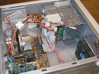
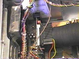
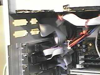
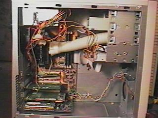
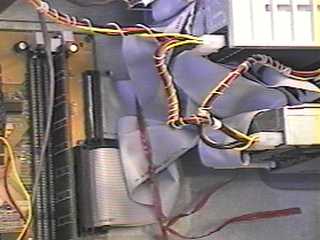
 The view above shows folded ribbon cables, they are
tied to the floor of the case and do not interfere with air flow. The "new"
fan is shown at right. I took out the fan holder, as in case mod below
and opened up the metal more. The fan is sealed against the front of the
metal panel with good old hard drive packing foam cut to size and secured
to the fan with DS tape. The foam is shaped inside, with a blade to match,
fan intake. Trial and error was necessary to insure no interference with
blades when is foam compressed. The fan has 2 wood strips hot glued to it's
frame. The wood strips are secured with more DS tape to bottom and side
of case putting just enough pressure on foam to compress it slightly to
form a seal.
The view above shows folded ribbon cables, they are
tied to the floor of the case and do not interfere with air flow. The "new"
fan is shown at right. I took out the fan holder, as in case mod below
and opened up the metal more. The fan is sealed against the front of the
metal panel with good old hard drive packing foam cut to size and secured
to the fan with DS tape. The foam is shaped inside, with a blade to match,
fan intake. Trial and error was necessary to insure no interference with
blades when is foam compressed. The fan has 2 wood strips hot glued to it's
frame. The wood strips are secured with more DS tape to bottom and side
of case putting just enough pressure on foam to compress it slightly to
form a seal.
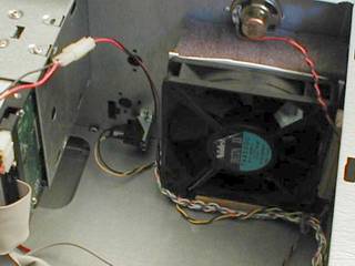
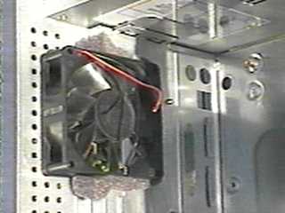
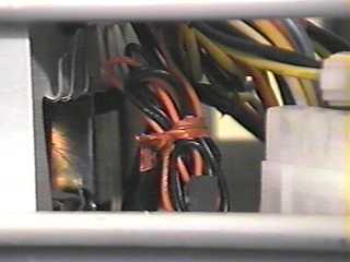
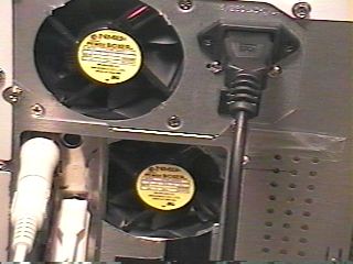
This $1.00, 12 cm, Nidec fan was a flea market find. It puts out a huge amount of air, but at 12v it was too loud. I'm running it at 7 volts and it is now quiet and still puts out more air than my best 80 and 92mm fans.
I had an open molex female connection so I just stripped about 5mm of insulation from the fan leads, folded bare wire back and inserted them into the molex. I usually splice or use wire nuts, but this was easier.
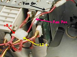
Picture shows technique to supply 7 volts. Fan positive
to 12 v as usual, but fan ground goes to 5 volt line.
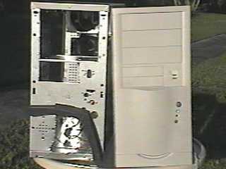
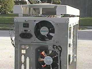
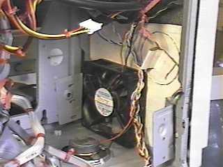
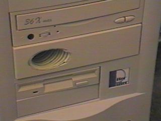
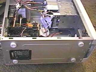
Above is a modified "Super Case" generic mid-tower. This is the third one I've modified and it's a little different than the earlier ones. They are usually available at shows for $25-40. It comes with a front plastic fan holder and metal bracket. This time I drilled out the bracket's rivets and it allowed me to open the case front more. The bottom of the plastic case front is cut out as much as possible to allow air to flow in freely. Case fan is mounted in back and guard cut from power supply. The stock fan in this power supply is very quiet and puts out plenty of air. It will stay till it gets noisy, then another NMB will go in. The pattern of holes in back is covered with clear tape, magic marker lines just to photograph better.
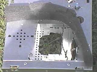
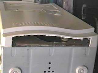
Front of case cut out with foam cemented to prevent warm case air from recirculating. Foam is cut, stacked, and glued to the shape of the case front. Front hole made with aviation snips, it's a little rough, but it's covered by case front. With the rear I tried a saber saw with a metal cutting blade. It was very fast, but vibration fatigued a thin piece of metal near the I/O plate and it broke. Since I didn't want anything else to break from the vibration, I switched to a Dremel tool with an abrasive disk. I don't what they are called elsewhere, but I buy them from dental supply houses as Separating Disks. It cut the metal like butter, so that will become the tool of choice for other cases. The down side of the Separating disk is the amount of very fine metal dust it produces. You need to vacuum and go over everything with a damp cloth to remove it all. In earlier cases I cut as large a round hole as possible and attached fan with double sided tape. Here I cut an almost square hole, leaving two existing holes for fan mounting and some space for foam in the other section, shown well below.
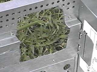
Here is a clear picture of the cut out I make in power supply cases to allow for better case ventilation. This power supply came mounted upside down compared to the other cases I've seen. Must have been a bad day at the factory in China:)
 Started to read in Newsgroup and Overclockers.com
that people were beginning to have luck with overclocking C366's. I went
to the local show last weekend with the intentions of buying a cheap all-in-one
socket-7 board and a Cyrix for a machine to replace a PCJr. Prices
for chip and board were unfavorable. One dealer had an Amptron 3748M and
another was having a sale on PPGA Celerons. Price for 366 was $4 more than
300A so I figured that was the CPU to get, since I didn't expect to be able
to OC on the Amptron. I bought a MSI v1.1 slotket. Before
I set up the Amptron in an idle AT case, I figured I'd try the 366 on the
BH6. The rest is HISTORY!
Started to read in Newsgroup and Overclockers.com
that people were beginning to have luck with overclocking C366's. I went
to the local show last weekend with the intentions of buying a cheap all-in-one
socket-7 board and a Cyrix for a machine to replace a PCJr. Prices
for chip and board were unfavorable. One dealer had an Amptron 3748M and
another was having a sale on PPGA Celerons. Price for 366 was $4 more than
300A so I figured that was the CPU to get, since I didn't expect to be able
to OC on the Amptron. I bought a MSI v1.1 slotket. Before
I set up the Amptron in an idle AT case, I figured I'd try the 366 on the
BH6. The rest is HISTORY!
 CPU is SL36C L9220529-0023 That
translates to an OEM PPGA Malaysian processor manufactured in week 22, 1999.
The week of manufacture seems to be
very important. The easy overclockers seem to be production from late teens
onward. PPGA processors have latest production changes, highest stepping. I'm using the same semi-large socket-7
heatsink I got for my Cyrix. I changed the fan to a 3 wire
one from a Cofan KC-266 so I could monitor fan speed. 2"
preheater hose fit the fan well without an adaptor. There is some Velcro
at intake end of duct and case to put a slight pressure on fan to hold everything
in place.
CPU is SL36C L9220529-0023 That
translates to an OEM PPGA Malaysian processor manufactured in week 22, 1999.
The week of manufacture seems to be
very important. The easy overclockers seem to be production from late teens
onward. PPGA processors have latest production changes, highest stepping. I'm using the same semi-large socket-7
heatsink I got for my Cyrix. I changed the fan to a 3 wire
one from a Cofan KC-266 so I could monitor fan speed. 2"
preheater hose fit the fan well without an adaptor. There is some Velcro
at intake end of duct and case to put a slight pressure on fan to hold everything
in place.
 I didn't expect to be able to run the
300A overclocked on the Amptron 3748. People seem to like to
say evil things about PC Chips boards. I've had a VXpro and TXpro running
Cyrix 686's and MII's, and some DLC boards. I've been happy with
all of them. This board has everything built in, but the kitchen sink, but
it is available as an option. Sound, SIS 3D video, 8MB shared, and
PCtel modem all seem to work fine. Will the video be ideal for intense gaming,
maybe not, but it won't be used for that.
I didn't expect to be able to run the
300A overclocked on the Amptron 3748. People seem to like to
say evil things about PC Chips boards. I've had a VXpro and TXpro running
Cyrix 686's and MII's, and some DLC boards. I've been happy with
all of them. This board has everything built in, but the kitchen sink, but
it is available as an option. Sound, SIS 3D video, 8MB shared, and
PCtel modem all seem to work fine. Will the video be ideal for intense gaming,
maybe not, but it won't be used for that.
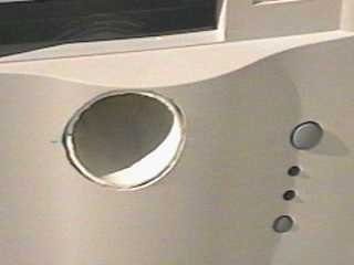
None of the external adaptors extend into
the case more than 1½ inches. No places for dead hot air here.
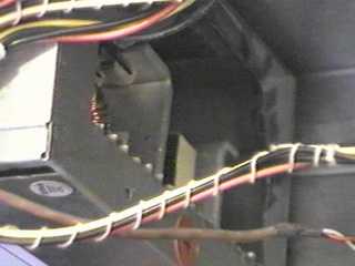
 There is not enough room for a full size
fan at case rear, as I prefer, so I had to go with an intake fan. I popped
the port cutouts to allow for more air flow out. As soon as I'm sure I won't
need any cards in the slots, which would involve moving I/O ports to this
spot, I'll open up this area.
There is not enough room for a full size
fan at case rear, as I prefer, so I had to go with an intake fan. I popped
the port cutouts to allow for more air flow out. As soon as I'm sure I won't
need any cards in the slots, which would involve moving I/O ports to this
spot, I'll open up this area.
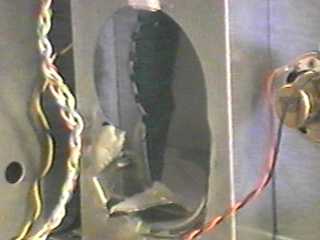
This AT case had an internal hard drive
bay below power supply. This needed to be cut out in order to install the
slot-1 motherboard. One thing I like in a $17 case is that the metal is
thin and easy to cut. One dislike is since the metal is thin and the motherboard
tray bends when reinstalling slot-1 processor. Next time tray is out
I'll reinforce it.
 This case also had a power supply that
had some loose wires when first purchased. A little bit of soldering was
all it took for a fix.
This case also had a power supply that
had some loose wires when first purchased. A little bit of soldering was
all it took for a fix.
The power supply got similar treatment as in ATX case, but I didn't feel like removing it and taking it apart, so slots were just snipped and bent up in place.
All the power cables were tied with twist
ties to reduce air resistance. Ribbon cables were separated into bands of
5 connectors, stacked and also secured with twist ties. My earlier attempts
at cable wrapping were with continuous cotton cord. Twist ties are easier.
Case modifications in front included removing a support to make room for an intake fan and port for CPU duct. Cardboard was used to enclosed intake area. Foam is attached to case front to seal area. Fan is NMB 2-speed; in case front it never speeds up, but shorting across the thermistor kicks it into high if I need it. Bottom of plastic face opened up to allow airflow to fan and duct. Since this picture was taken I hot glued caps from 2 liter soda bottles over the feet to make computer sit higher from surface. I will need to make an adaptor for a duct to raise it over the memory. There is a little less room than with the BH6. I picture it as a box with a triangular profile, or maybe I can get lucky and go back to salasa cups, makes a great excuse for take-out. The heatsink is a Cofan KC-266 that I shrouded like the Intel retail.
Results? 300A retail 9840 running at 450MHz. Bus speed adjustable in BIOS, no taping of B-21 needed. CPU was stable @ 1.9 volts on BH6 so no problem @ 2.0 volts here. I'm going to be making one for my nephew who wants something small and inexpensive to use at home and work for Internet only. We'll go PPGA with MSI slotket so voltage can be adjusted if necessary.
I'm going to try to NOT test the Celeron 366 in this computer. I've always liked this Mini-tower case as much as I hated ATX cases in general. No point of being happy running 550 in AT case because I need a third external bay for removable hard drives.
I had a retail Celeron that needed 2.4 volts before becoming stable @450 MHz. I replaced the retail heatsink compound with RS paste, but it had no effect on the chips ability to overclock. I'd been reading the newsgroup, alt.comp.hardware.overclocking, and going to the various Celeron sites. CPU and case cooling seemed to be a very important issue. I don't understand why this method of aiding the cooling of the CPU has not been posted before. I know it's not as exotic as a whole bunch of fans or water cooling with the water source from a fish tank, but it's cheap and easy. Most of the materials are readily available, especially if you never throw anything out.
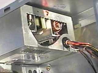
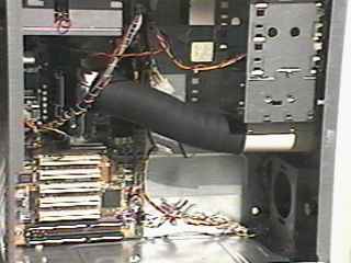
I duct the retail heat sink's fan directly to the outside.
One major issue in case cooling is to lower case temperature so heat transfer
from CPU will be more efficient. With the fan pulling cooler air from
outside the case, heat transfer should be increased.
Power supply and case fan below it both exhausting air. There is a large
square cutout under the lowest card. It's a cable modem receiver and
is my biggest heat producer by a long shot. The change from blowing
in at the bottom front reduced MB temp. 5° C. Small holes
in back taped up starting at third row.
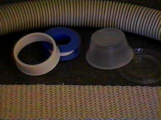 Materials: Light weight vacuum hose from a
broken shop vac. Cover from roll of Teflon tape. Cap used was
red, from Water Whiz brand, sold by Home Depot. Cap is notched for
power connection and lined with non-slip matting for a tight fit over fan
housing. Felt would also work. Rubber cement on both surfaces
is the easiest method to hold matting and plastic together. The Solo PL2
cup is a standard at almost every take-out. Mine came filled with
Pollo Tropical Salsa, you do have to empty it before use. Make a hole
for the hose and line with the matting. So far I had to spring 99 cents
for the tape, I already had a lifetime supply without a cover.
Materials: Light weight vacuum hose from a
broken shop vac. Cover from roll of Teflon tape. Cap used was
red, from Water Whiz brand, sold by Home Depot. Cap is notched for
power connection and lined with non-slip matting for a tight fit over fan
housing. Felt would also work. Rubber cement on both surfaces
is the easiest method to hold matting and plastic together. The Solo PL2
cup is a standard at almost every take-out. Mine came filled with
Pollo Tropical Salsa, you do have to empty it before use. Make a hole
for the hose and line with the matting. So far I had to spring 99 cents
for the tape, I already had a lifetime supply without a cover.
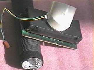
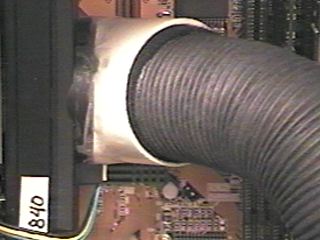
The intake end of the hose is hot glued in a hole on a
5¼" faceplate. It's an oval because I cut it to fit a
small mouthwash bottle. The setup was very elegant, with a lined cut
off plastic bottle over the fan and very flexible ribbed medical gas tubing.
Unfortunately the diameter was too small and cooling was reduced.
It was very easy to work with. I'm a dentist and haven't seen the
inside of an OR since my residency so I don't know how big current tubing
runs. Nitrous oxide tubing is too small.
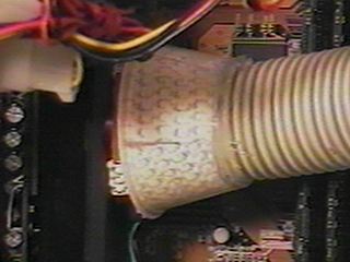
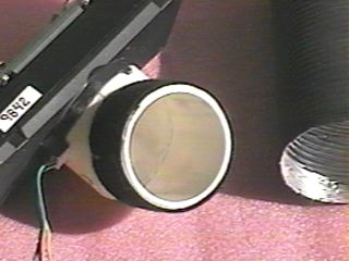
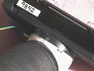
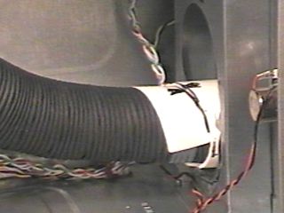
Here is a close-up of the cover over the fan and the hose and it's Solo cup coupling over it. The relative positions of the parts are shown in the next picture. Hose length is so there is slight pressure on the cap so everything will stay in place. The hose will go in at an angle so cut and hot glue to the Solo when it looks right. What would be more desirable would be a flexible duct, like mini cloths dryer ducting. With proper size flexible duct, a small snap lid container could be cemented to the fan and the duct to the lid. This would eliminate the liners and give a more air tight fit.
You don't need Sandra to check your fan, just place a finger near the top of the duct.
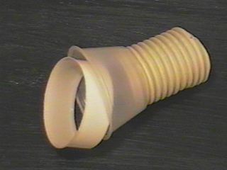
I was told that there was 1 7/8 inch auto air conditioner duct available. That would have been my "ideal" duct material. Search at 3 big parts stores only yielded 2½ inch stock. I don't think I'll keep looking because I did find Preheater Hose that did the job beautifully. All stores carried it in sizes from 1½ to 2 inches. I think this is the same as the pipe from an old Beetle someone talked about in the news group. It's made of foil and is paper coated in most sizes. It bends to any needed angle and remains tubular. It cost 2 to 3 dollars a tube depending on the length.
 1½ thin-walled PVC pipe was used for the connections.
It has the same outside diameter as the retail heat sink's fan shroud. The
1½ " hose fits inside the pipe, with thin felt rubber cemented
to the paper cover. To use 2" hose you attach thin felt
to outside of pipe with double stick tape.
1½ thin-walled PVC pipe was used for the connections.
It has the same outside diameter as the retail heat sink's fan shroud. The
1½ " hose fits inside the pipe, with thin felt rubber cemented
to the paper cover. To use 2" hose you attach thin felt
to outside of pipe with double stick tape.
I used a hand circular saw to cut an angle (about 60°) in pipe and for
length cut. Edges were smoothed with sandpaper, or model trimmer
if you are a dentist, and cemented together to form custom elbows. Notches
are cut to fit fan. Will need trial and error to get good results.
Remember to count fingers after each cut.
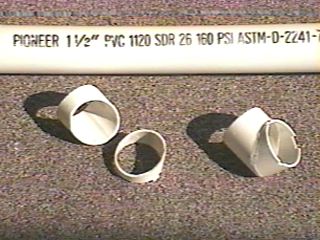
Above are the hoses and elbows for the 2" and the 1½" hoses. I planned to hot glue the elbows to the fans and just trial fitted with Scotch Magic Tape. The taped joints were very strong and it sealed any small gaps. I'll stick with the tape; so will the elbows.
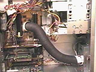
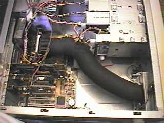
The hoses in place. The 2" hose exits in front of the case through holes in metal and plastic panel. The 1½ hose goes through a hole in the metal only and into the space behind the front panel. The bottom vent area in the plastic panel has been enlarged as much as possible. If I do another it will exit at bottom. The hoses hold their shapes and don't put any force on the CPU board.
The terminal end of the hose could be flattened into an oval shape and go through a 5¼" external bay like the vacuum hose in my earlier attempt.
Here are the connections to the elbows for both. There is also a 1 3/4" Preheater Hose that is an exact match for the pipe outside diameter, but was solid foil, not paper coated. It would also have to be taped to the elbow. The pipe has to be removed to access the memory slots in the Abit BH6.
I did make a change in the 2" exit since this picture. I hot glued window screen to the end of the pipe since my Grandson, pictures on site, might find it a useful place to store grapes and stuff. The smaller hose fits loosely in some pipe hot glued to the case for the smaller duct. A label on the pipe with line and arrows let me replace the hose exactly. You can't see it here, but the metal with the pattern of holes in front of the fan holder has been cut out. The vent at the bottom of the plastic case front has also been opened as much as possible allowing for free flow of air in case.
 I replaced my power supply fan with my last NMB fan. They
are so quiet it's hard to believe. They are model 310NL-04W-B10. I
don't think they are made any more, but similar units are still in production.
The blades are rounded, I think that is why they are so quiet.
Since this picture was taken I replaced
the power supply fan with a temperature controlled NMB model 3110NL-04W-B57.
I bought a lot of six power supply pulls on eBay, the lot was under $14
including shipping. The dealer has a few hundred fans and regularly sells
lots of 6. Do a search for "NMB". At low speed they
are a quiet as old fans, high speed is a little louder with significantly
higher airflow.
I replaced my power supply fan with my last NMB fan. They
are so quiet it's hard to believe. They are model 310NL-04W-B10. I
don't think they are made any more, but similar units are still in production.
The blades are rounded, I think that is why they are so quiet.
Since this picture was taken I replaced
the power supply fan with a temperature controlled NMB model 3110NL-04W-B57.
I bought a lot of six power supply pulls on eBay, the lot was under $14
including shipping. The dealer has a few hundred fans and regularly sells
lots of 6. Do a search for "NMB". At low speed they
are a quiet as old fans, high speed is a little louder with significantly
higher airflow.
The two pictures above show the bottom
of the case and the front intake port. The plastic face is cut out at the
bottom to allow for good airflow. The computer is on it's side on a stand
I made from plywood and 2x4's. It has casters and keeps the computer 6 inches
off the carpet. I allow the plastic face to hang over the front edge for
least restrictive air flow. The cutout in rear of case bottom is right under
the cable modem receiver, it produces a lot of heat, blocking it off increases
motherboard temperature 3°C. The close-up of
the front port shows the cut out and the foam that seals off the top of
the case front from intake. I reasoned that without it separated from
the rest of the case I could recirculate warm air to my duct. Not
hard to do. With front off cut packing foam, from hard drives, ect., to
approximate shape of case front with a little excess. Closing it up puts
pressure on foam and it seals the area.
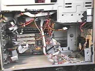
The pictures above other things done in case for less restrictive air flow. The ribbon cables are folded and twist tied to bottom of case. Can't see in picture, but unused stand-off holes are uses to anchor ties. Use extra stand-offs or plastic case thumbscrews. The power supply has been opened up to help get air out of computer. It also reduces fan noise. Fan guard also gone as seen in earlier picture.
I don't have provisions for measuring CPU temperature, but I got a message from a visitor here, also a dentist, who made modifications to his system after seeing the above. His positioning the duct behind an intake fan probably boosts the airflow through the heatsink without significantly increasing the air temperature.
" I tried the 1 1/2 inch ID pvc with a 2 inch preheater
hose positioned in front of the front lower
intake fan. The hardest part was getting the correct angle on the pieces
of angle cut pvc. I cut a lot of pieces till I got it right. You are correct
that using a model trimmer makes this a lot simpler. Heeding your advice,
I did count my fingers. No problem -- I started and ended up with 11.
My CPU runs 4 degrees C cooler and my motherboard run 2 degrees cooler."
A second E-mail with setup similar to mine
also reported 4°C CPU temperature drop.