(a rolling account of my A65 restoration)
This restoration is not complete so new sections will be added as the work progresses
I can still remember buying a copy of "The Motorcycle" in 1966 and opening it up to see the double
page coloured advert for the BSA range for the year. I was 16 years old and would have given anything
to have owned one of those machines. They had a real aggressive, masculine line to them and seemed
to ooze power and speed. Not like those prissy Triumphs.
I didn't see anything of the BSA unit twins for another twelve years. I had
received the usual answer most
young kids get when they announce to their parents that they want to buy a motor bike - NO.
It was
now 1980 and I had been riding a Suzuki T250 for about a year and was keen to get a British Bike to
do up. The bloke I had bought the T250 off had just finished doing up a Commando 750 Interstate
which started out as a basket case and it looked terrific. He had put me onto the name of a local Bathurst British bike repairer
who might know of a suitable bike. The result was I bought a January 1970 Royal Star from a fellow in
Orange.
The name Royal Star seemed a good name at the time. I had heard about the BSA Gold Star so I
supposed a Royal Star must be similar. My knowledge of BSA motorcycles increased when I bought a
copy of Roy Bacon's BSA Twins & Triples. I was to find out that Royal Star unit twins were not held
in such high regard. In fact the writer of the Classic Bike article of 1979/80 clearly was not sorry to see
A65/70 production cease in 1973. Stories of hand numbing vibration, disintegrating engines and bikes
that disassembled themselves as you ride seemed common and then of course the notorious A65
bottom end. There are as many opinions on the A65 main bearing problem as there are riders.
But none of that mattered when you have actually got your own 1970 A50 sitting in your garage and
you can dream of how it will turn out. Over the next 6 to 8 months I basically did a cosmetic rebuild
on the bike. The engine was running well so little was done to it. Unfortunately I ran out of money
before the project was fully completed. Our youngest daughter had just been born and there was no
more spare money for motorbikes. In fact my wife saw the bike as competition so it was less than
popular. I had managed to get the bike registered but the front forks needed new stanchions and I
didn't have the $200 needed to finish the job. So I sold it to a dealer and got a good price for it. Enough
money to be able to buy a new Jap bike, which depreciated to less than half its purchase price in 12
months.
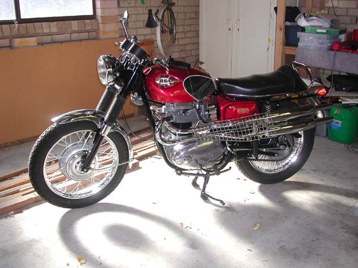
It was now 20 years later and I had become aware of my advancing years and had been reminded of my mortality fairly conclusively so decided when I received some money from my mother's estate to actually spend some of it on myself. I started to look around for suitable bikes and basically had decided to try for a 1968-70 Bonneville. As a result I have a whole lot of books on Triumph twins and the Bonneville in particular. It was in the December issue of Just Motor Bikes that I first saw it. The picture in the ad looked great and the bike had clean uncluttered lines. No exhaust pipes to spoil the looks of the machine as the picture was taken from the right side and it was called a Firebird. With a name like that it had to be good. It had done a claimed 5,000 miles and the advert said "presents near new".
I contacted the owner who turned out to be in Airly Beach
North Qneensland. He sent some photos by email and in
due course I caught a Virgin Blue flight to Brisbane and Greyhound coach up to Airly Beach. The bike
looked OK and it started easily although was very noisy. Perhaps I should have had a ride but I was
very reluctant to run the engine for any period of time till I had changed the oil. As I hadn't ridden a
bike for 20 years I also didn't want to make a fool of myself by falling off and damaging the bike. I
should have checked it over more thoroughly but I guess I was too quick to believe it had really only
done 5000 miles. Now I know it was only the speedo that had done 5000. Anyway the deal was agreed
on with the owner paying the freight to Sydney and I arranged for the shipping up to Bathurst. Didn't
look quite as good as the picture but to actually have it in your own garage is a great feeling.
I had decided to try to be as methodical as possible in the disassembly of the bike with all parts being
removed cleaned and then packed away in boxes and wrapped in plastic or between foam plastic. I had
no intention of rushing this rebuild as I had no timetable to keep to. Gone is the urgency of youth and
the restoration process was to be much an enjoyment as the riding would be. Bikes are after all just big
Meccano sets. Having discovered British Spares in New Zealand and their amazing stock of parts at
such good prices I decided to replace anything that looked a bit tatty. As a result I have spent a lot more
than originally intended on all sorts of bits and pieces. My desire was in effect to turn this into a new
bike.
It rapidly became clear to me as I discovered one worn out part after another that this was not a low
mileage bike. Many parts that looked OK when I saw the bike in QLD turned out to be lightly corroded
and in some cases deep corrosion had been painted with silver paint to disguise it.
The bike had on close inspection quite a lot of corrosion affecting every part that wasn't painted.
Alloy parts were affected by the salty atmosphere of North Queensland and would require a lot of
buffing. Virtually every nut and bolt was corroded. From a distance they just looked dirty but the dirt
didn't clean off. Thankfully the tank was in very good condition with just a few paint chips to get it
back right and the guards were fine.
What had started out to be just a cosmetic rebuild was now going to be much more extensive. I wasn't game to think about the engine at this stage so I just put that out of my mind and set about pulling the cycle parts apart. The frame was in good shape and the paintwork very good with just some paint removed by chafing cables. I touched up these areas with aerosol cans and for small areas they work out OK. Don't try painting large areas as you need good spray equipment for that kind of task.
The owners friend had lent me his copy of a BSA workshop manual and parts list for 1969-70. These
were actually photocopies of manuals originally belonging to the QLD Police so we can assume that
the QLD Police used A65 motorcycles. I made copies of these manuals and they have proved
invaluable. However, it is important to seek out as many sources of information as you can find.
Frequently they will each give a different slant on the topic eg. the factory manual always says "use
BSA special tool xxx" which is not a lot of help when you cannot obtain that tool. Haynes A65
Workshop Manual on the other hand often suggests a method using tools that the ordinary rider
might
have or can easily obtain and for this reason alone it is worth the cost.
When I discovered British Spares I bought a copy of their 1970 BSA A65 parts list which only cost
$10 NZ. This has become my most read book and I carry it to work with me in my bag just in case I
get the urge to order some part or other.
My prime reason for joining the club was to have access to like minded people who could advise me
when I ran into problems. Shane Phelps has been helpful on a number of occasions and also Andrew
Gunn and I am sure they will continue to be in the future.
The Internet has become so much a part of our way of life these days and I have found it an invaluable
source of information. Below are a couple of interesting links that you might like to look up. Some
sites have technical articles on a variety of repair procedures.
Another source of information are the various parts suppliers who are usually very happy to advise
you, particularly if you are a known customer of theirs. You do at times need to be a bit wary and seek
confirmation from other sources. I have found British Spares very helpful but when you consider how
much I have spent there I think I must just about have shares in the company.
My last information resource for the rebuild was Roy Bacon's "BSA Twin Restoration". This is an
excellent book providing details on all the changes of parts and panels over the life of the BSA Twin.
You must realise that Roy isn't always correct and again seek out other sources if you are in doubt. In
time you will become an A65 expert like the rest of us and be able to spot a non-standard tire valve
from 50 paces.
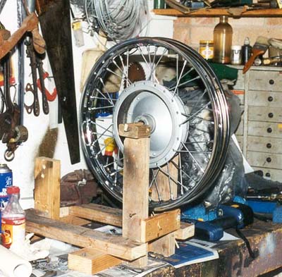
The chrome rims and spokes had to be replaced and the wheel bearings were all worn. I was able to buy new sealed bearings from a local bearing service shop and rims and spokes from British Spares. As the circlips and grease retainers were cheap I bought new ones as they tend to get knocked around when being removed. I had intended to send the wheels away for rebuilding but after reading some articles, which encouraged restorers to have a try, I decided to give it a go and build them myself. I made a stand to mount the wheel in, out of 4x2 radiata pine. This stand also doubled as an engine stand and was a copy of the one I had made up for my first bike back in 1980. Then I used a couple of long woodscrew driven through the stand to indicate rim runout in both planes. This could be adjusted in and out and had the points filed off to prevent the rim being scratched. I had painted the inside of the rims with zinc chromate paint to help reduce the chance of rust and had fitted rubber rim tapes. I just took my time and was very surprised at how easy building the wheel was. It was explained to me that if necessary you can spend a couple of days setting the wheel up but a wheel-builder has to do a quick job in order to make it pay. I have tried to use this policy in all that I have done and so far it has paid off. So my advice is don't rush the job but allow time to solve the various problems you experience. Better to do nothing rather than make a pig's ear of the job.
These were stripped down and the steering head balls replaced. I would have liked to fit tapered
bearings but the only ones I could find were from SRM and quite expensive. New handlebar clamp
bolts were bought from Classic Fasteners and new rubber instrument cups from K&M in Adelaide.
Fork bushes and seals were replaced and the legs were pulled up into the yokes using a homemade
puller lent to me by Shane Phelps of the NSW BSA Club. This tool is a rough copy of the special BSA tool and does a good
job. Early on I had decided to buy whatever BSA special tools I could get from British Spares at a
reasonable price. I believe one of the factors that prevents the backyard restorer from doing a good job
is the lack of the right tools. As a result I have accumulated a number of tools that will probably be
only used once. A tool which is essential is the fork seal holder spanner and another handy one is the
fork top nut spanner. I am still not 100% happy with the fork stanchions as there is some wear evident
on the legs. This concern can wait for now and I will check it when the bike is on the road.
Deciding on the right tires took me some time and initially I bought a Avon SM Mk II, through a local
Triumph dealer in Bathurst and it cost $180. In the end I also bought a Dunlop K70 from Ryans for
$90 for the front. The Avon has a very deep profile and with hindsight I should have bought a K70 also
for the rear. TT100's were unavailable in the right size. The bike had come with a worn Bridgestone on
the rear and a new Avon AM20 on the front. The AM20 is a modern low profile tire and just didn't
look right on the bike. The K70 looks just right.
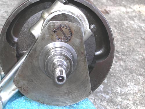
I was keen to get the wheels on the bike and had to buy new front and rear wheel spindles. The
bearings had been turning on the front spindle and although Loctite might have worked I decided to
replace where I could get the parts cheaply. The front brake linkages were sent away to Pine Rivers
Electroplating in Queensland to be satin chromed and came back looking just perfect. Pine Rivers have
done good work for me with the various nuts, bolts, springs and grab-rail that I have had plated. They
did lose part of one of my orders but it was only a couple of washers and two bolts. I couldn't say how
good their work would be on larger items such as tanks.
The front and rear brake linings were worn but still had some life so I have left their replacement till
some future time. By now I was getting concerned with the amount of money this project was soaking
up.
Having installed the forks I was able to fit the front wheel, which just didn't look right as it appears to
lean to the left at the top. This can only be caused by the axle clamps not clamping up squarely. Rim
offset had been carefully set to the original amount so at this stage I am not sure what the problem is.
This is one of those problems that I am leaving while I wait for a solution to present itself. I am also
concerned that the stanchions are bent although this was not evident when I had the forks apart.
The Internet has been put to good use searching for all sorts of information about A65's and what parts
suppliers are out there. As a result I have spent a lot of money buying parts by email from British
Spares in NZ. They have what must be the most efficient order system I have come across and they are
cheap. Sometimes they are out of stock of certain items but it is worth waiting for the new stocks to
come in as their prices are half what you would pay in the UK or US. Mailing cost from UK and the
US are also very high. An example is the H exhaust pipe joiner which I bought from British Only
Motorcycles and Parts of Michigan USA. The cost was $34.31 plus $25.16 shipping which brings it all
to $59.47 US. I would suggest you only buy from UK or US suppliers once all cheaper sources have
been tried. You do need to be careful with British Spares as they often substitute a different part for the
one you want. It is frequently a Triumph component and very similar but sometimes not close enough.
Other suppliers I have used are Burton Bike Bits, British Only, JimEade, Ryans of
Parramatta and now Gloucester, Modak Motorcycles, Mike's Classic Cycle Spares in QLD, Baxter Cycle in the US, Hamrax
in Kingaroy and
K&M Motorcycles in Adelaide. Most of these dealers have been very good but I have
found Burtons
difficult to deal with. They supplied a wrong part and finally offered to refund my money
after I took
my case to consumer affairs in England. However, they would not refund the mailing cost
which was
actually more than the part itself. Hamrax supplied some useful parts but were very slow,
hopelessly
disorganised and supplied incorrect parts despite being supplied with part numbers. I have found that
all suppliers make mistakes but the good ones accept their responsibility and refund and
exchange the
goods.
I can recommend British Spares, Mike's Classic Cycle Spares, Jim Eade, Ryans, K&M, Baxter Cycle,
Modak and British Only in Michigan USA. Classic Fasteners of Adelaide have been excellent in
supplying nuts and bolts, taps and dies etc. Their service is reliable and readily exchange parts where
needed.
Chrome plating was done at Pine Rivers Electroplating of Lawnton, Queensland. They zinc and chrome plated many special bolts and nuts for me and in general did a good job. They also chromed the rear grab railand satine chromed the front brake linkages.
Early on I decided to buy a polishing kit for buffing the alloy parts. British Spares stock a kit for $65 which consists of three buffing wheels, three grades of abrasive compound and a conical shaped felt bob. These kits do make the job of polishing a lot easier but preparation is still needed. On many occasions I would have to start with wet and dry to remove the deeper pitting. Often I found that it was like a dog chasing its tail with one pit being removed and others appearing as though they were conceiled below the surface. Care needs to be taken when buffing as the fine gritty particles will settle on everything in your garage and could damage car paintwork. Wear protective goggles and ear muffs and cover as much of your face as possible as you will be covered in a greasy coating. I tried alloy deoxidising liquid, which contains acid and is diluted 20:1. I would suggest great caution when using this liquid as it penetrates into the pores of the alloy and is difficult to wash off. I had to buy a 5 litre bottle of the stuff so have enough to last a lifetime. Actually I found that it didn't work all that well on smooth surfaces but did help with sand-cast alloy surfaces if you used it with a wire brush. Perhaps if I just used the wire brush it would have worked just as well.
As said earlier I have attempted to replace any nut or bolt that was corroded. I bought a bulk pack of
zinc plated UNF nuts, bolts, washers and nyloc nuts. This pack has been worth the expense even
though I have quite a few left over. In cases where appearance was important I have replaced with
chrome or stainless steel. A very good result can be achieved with stainless by filing off the lettering
on the bolt head then polish the head first with a oil stone and finally with the buffing wheel. If you
follow this technique the head should shine like a chromed finish but will not rust. There is very little
difference in cost between chrome and stainless but if you can make do with zinc you will save a lot.
There were many parts that were in good structural condition but just needed plating. I sent various
special bolts, nuts and springs for zinc plating. Zinc plating is cheap and can look just as good as
unpolished stainless. In many situations to use highly polished nuts and bolts would look out of place
and certainly not authentic. I have obtained a set of stainless allen head, bolts for the engine
sidecovers.
Quite a lot has been spent on the electrics with the harness being completely replaced with a pattern item from British Spares. The old one had been chopped around quite a bit so felt this was a worthwhile cost. The bike came with Boyer Electronic Ignition so some modification of the harness is necessary. The Firebird has a 5" headlamp as standard but my bike came fitted with a 7" Lucas unit. Unfortunately this lamp was not correct even for a 1970 Lightning as it didn't have the ammeter hole. Both the shell and rim were rust pitted so these were replaced with a correct unit with the ammeter hole. I was able to get the correct headlamp bolts from Ryans but the spacers were very elusive and were finally tracked down at Mike's Classic Cycle Spares in QLD. A QI headlamp insert had also been fitted. I do not like the small Firebird lamp which to me looks too small and must be rather weak for night driving. The rear lamp lens was broken in shipping of the bike from QLD but this was no problem to obtain. I suppose there was no need to replace the zener diode but it looked like it would give me trouble so I replaced this also. I have tried to use heat shrink plastic tubing where possible to seal out the weather and help hold bullet connectors together.
The alternator cable had been attacked by the chain
so I had to cut the wires and graft on two new ends with the join being again
sealed with heat shrink. At this stage it appears that the alternator stator was
fitted back to front as the cable exited from the inside and not the outside.
This meant that it came close to the primary chain which had worn into the
insulation.
As I am something of a novice with engine rebuilds I left this part of the rebuild till last. I gradually
removed bits here and there but eventually was faced with removing the head. This proved to be no
problem but revealed that the engine was probably on its second rebore as there was a 755 punched into the
piston tops. The bore looked OK with very little in the way of a lip at the top. There was however a
patch or stain that could be corrosion half way down on one bore although no corrosion on the rings.
Another case of very poor storage in a corrosive atmosphere. My current hope is that a hone might be
sufficient to clean up the bores. When I first got the bike I had removed the plugs and squirted quite a
lot of oil through the plug hole and then cranked the motor over a few times. I have not attempted to
measure the bore wear at this stage but have just sealed the barrel in a plastic bag and stored away for a
later time. The same applied to the head, which has also been stored and will be looked at later on.
Removing the oil pump revealed that the ball valve could not have sealed properly as the gasket was
touching the ball and preventing it from seating correctly.
I was getting closer and closer to that time when I would have to split the crankcase which concerned
me a little. I suppose I was worried as to what I might find. The gear cluster was removed as a whole
and stored away. All the books say that you shouldn't need to replace the camshaft or followers unless
your bike has done a high mileage and you guessed it, my camshaft lobes were worn with two having a
lip on one edge and some chipping where the lip had broken away. The followers were worn to match
the lobes and luckily I was able to get a new set from British Spares.
The day had finally come and I had removed all the bolts and nuts that hold the crankcase halves
together. The manual says just strike the crankcase mouth with a hide mallet and it will come away. It
also says do not use a screwdriver or chisel to prise them apart as this will damage the jointing surface.
Well you have to be a little practical as no amount of hammering with a rubber mallet had any effect. I
resorted to some careful prising with a chisel and they came apart with very little damage. Any
bruising of the alloy could be cleaned up with an oil stone.
First impressions were of a butchered sludge plug and the area surrounding it. The oil that flowed out
of the bearings when I removed the conrods sparkled in the sunlight as the light caught the metallic
particles in the oil. Not a good sign and confirmed by the scouring on the big-end shells. The timing
side bush is scoured also by these metallic particles and will need to be replaced. There was a shim
holder in place behind the roller bearing but no shims and the thrust washer had some wear so will also
need to be replaced. Checking with a micrometer indicated that the main bearing journal and
big-end
journals appear to be on their first regrind (0.10" undersize). Wear is within the allowable limits so at
this stage I intend to replace the bearing shells and bush completely including the roller which is a bit
of a slug at $100.
I now agree with all the experts and that is don't bother trying to remove the plug with a impact driver. With great care I had drilled the 12 punch marks from the plug and after the abortive impact driver attempt I turned to a method I had read about on the Internet at http://www.geocities.com/MotorCity/Downs/9472/endplug.html
This method involves drilling a 10 mm hole into the centre of the plug. Then take your 10mm allen key and saw off a piece about 30mm long. This is then driven into the hole. A 10mm socket can then be fitted to the allen shaft and a socket wrench can be used to easily undo the plug. This sounded a little vicious so I filed six grooves into the hole using a small triangular file to produce a rough hexagonal hole. The allen shaft then will drive in much easier. I will replace this plug with a allen head version when assembling.
"And Then Withdraw the Sludge Tube Using a Piece of Hooked Wire
"
That certainly is a laugh and so like many statements in workshop manuals. I firstly wasn't sure if I
had a sludge tube. There appeared to be some thin metal pressed hard against the hole in the
crankshaft. It looked like someone had tried to remove it by screwing in a large tap but it hadn't
worked.
What followed was a saga that stretched over about 5 weeks with me trying to jam screwdrivers down
between the tube and the crank to collapse the sides in and thus break its grip on the crank tube. This
only partly worked and didn't do my screwdriver handles much good. As before I put this aside and
came back to it on a number of occasions but with little extra success. I emailed some of my sources of
BSA wisdom but still no solution. I had run out of ideas and as I am a Christian I did what a Christian
does when he needs an injection of wisdom, I prayed. Up to this point I had resisted involving God in
this as I have viewed building a motor bike as something God would show little interest in. How
wrong I was as I now realise that God wants to be involved in all we do no matter how minor. That
Saturday I went out to the garage convinced that I was going to beat that sucker one way or the other. I
drilled into the centre of the crushed end of the tube with a large drill bit and this tore away part of the
wall revealing a clean edge. It was then that I realised how to remove it. Using a large screwdriver like
a chisel I cut into the edge of the tube and slit it down its full length. When I tried to withdraw the
driver the tube came with it. It had all been so simple and so quick.
Although the inside of the tube was fairly clean the space between the tube and crank was dirty, gritty
and not at all nice so I am so glad that I removed it. This went to convince me that I had done the right
thing in buying a cartridge oil filter from British Spares. That along with frequent oil changes should
ensure reasonable engine life. The filter kit is designed for a Triumph Twin (pre OIF) so I need to
make a mounting bracket for it. i have been a little concerned at the drill holes around the sludge
tube
hole. Some have suggested that the holes provide a weak point where cracking of the crankshaft can
start. I have since consulted with a couple of people whose opinion I respect and they have said that it
should be OK. I guess I will have to make sure I treat the engine with some tenderness and not run it at
high revs for long. From what I hear the vibration should alone prevent that happening.
After splitting the crankcase the camshaft was removed and although the right side bushes were fairly
good the left hand blind bush was a wobble fit with the camshaft. I was then faced with the problem of
how to get the bush out. Haynes manual said to obtain a large Whitworth tap and screw it into the bush
then insert a large bolt, clamp the bolt head in a vice and drive the casing off the bolt with a hide
mallet. I was able to obtain a 7/8" UNC tap for about $35 from a local bolt shop and screwed it into the
bush. Then I heated the casing to 450 F and clamped the tap in a vice and using a rubber hammer I
drove the casing off the tap.
I am waiting to get my camshaft as Mike Reilly has proved very difficult to pin down as he seems to
spend most of his time in the US buying bikes. However, I am determined to catch him when he
returns mid December. Big end bolts are also a problem and am waiting on a new supply arriving at
British Spares.
It is now some months further down the track and I have obtained a new 0.010" undersize timing bush
and big end shells. Using my new micrometer I measured the bearing journals and it looked like they
were all on their first regrind. Andrew Gunn and Shane Phelps had suggested I get a timing bush which
consists of a steel casing with a bronze bearing surface. My old bush was of the older all bronze type.
Recently I attended a wedding of a young relative of my wifes. The groom's father is restoring a
Vincent Rapide and I was able to ask him to come and give me his opinion on the crankshaft and
barrels. Brian is a very skilled metal worker and is completing his fitting and turning trade certificate at
TAFE. He works for the RTA as a civil engineer. Brian was of the opinion that the
bores looked OK. I have checked ring gap at top and bottom of each bore and it looked like there was
only 0.0015 difference. As this is within the 0.005 limit I was relieved. He suggested I go and see John
Fraser who has a engineering business in Bathurst and get him to measure the bores and bearing
journals to decide what was the best course of action.
I have now been to see John Fraser and have come away quite impressed. He runs his business from a
old building in South Bathurst and has a very well equipped workshop. His income largely comes from
driving school buses but with the rest of his time he reconditions engines. John is currently examining
my barrels, pistons, rings etc to decide on the best course of action.
From his initial inspection it appears that the engine is already at 0.020" oversize and fortunately the
bore wear from bottom to top is only 0.0015". I have also been concerned about scouring near the top
of the bore and also on the piston just above the top ring. My concern being that I might need to rebore
just to get rid of the scouring. If I go on the opinion of Brian Maloney and John Fraser then it should
be unnecessary which is a relief. John was saying that the cause of scouring at the top of the bore
is
poor air filtration. The gritty particles being of a much greater hardness that cast iron. I guess this is a
warning to those of you who like to run your bikes without air cleaners.
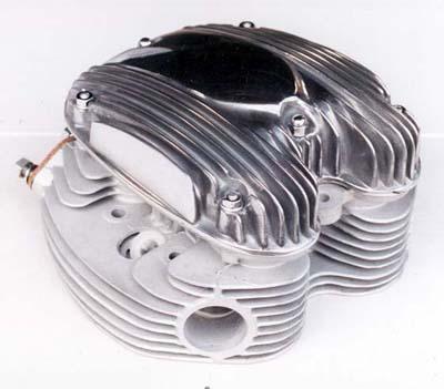
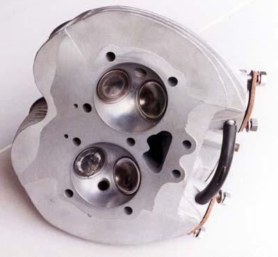
At this stage it looks like I will get John to recut the exhaust valve seats, bead blast the fin area on the
head to clean it up and grind the head face. There is a possibility that new pistons might be needed as
the pistons have 755 stamped into their crowns. I have taken this to mean that they are 75.5mm and
would therefore be 0.020" oversize. If this is the case then I have 20 thou pistons in a 40 thou bore. I
have reached the point where nothing would surprise me now.
It is now January and John Fraser has finished all of the work on the engine components. He did the following:
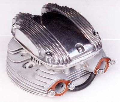
The head recondition is completed and looks very nice now that it is bead blasted. The valves and guides were OK but the seats needed grinding and had become slightly pocketed. He machined the head face as it was clear from the gasket that we were not getting a good seal between the cylinders around the middle head bolt.
One area of concern was the fitting of the new second hand camshaft to the new bushes. John found that the three bushes did not line up correctly. He had to bore out the left hand hole in the casting and then make up a new bronze bush drill the oil hole and machine in the oil grooves. This added quite a lot to the cost of the work.
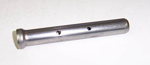
While I was dealing with John Fraser I also got him to make some minor changes to an alloy sump I
had bought off SRM. These items are of a good design but machining is not perfect. Also got John to
turn down a front fork top cap which I am going to make into a front stanchion puller with the addition
of a bit of threaded rod and a piece of tubing.
Next step is to start the assembly by bolting up the cases with the crankshaft to check the end float. I
am still waiting to get the new conrod bolts from British Spares. They must surely be arriving soon as
it has been at least 3 - 4 months so far. Some things just can't be hurried.
Weeks later I am still trying to get some new conrod bolts and have tried all the usual sources. SRM
don't have any and neither does C & D Autos. K & M Autos don't have any stock and they buy their
supplies from British Spares. The mechanic at K & M said that he doesn't replace the bolts so I was
left with the decision as to what I should do. I was saved from deciding because I found a classified in
the latest Just Motor Bikes mag for a set of A10 conrod bolts and nuts. Apparently the late model A10
bolts are the same as A65 (67-1536) so in due course they arrived at the post office by COD. They
look to be well made and nicely polished.
In order to determine the crankshaft end float it was necessary to assemble the
crankcases with
the crankshaft and camshaft in place. The crank shim holder is positioned between the crank web and
the roller bearing and following crankcase assembly the amount of float is measured with a feeler gauge. To do this the crank has to
be moved to the left and right in the casing with the clearance measured each time. By subtracting one
from the other you arrive at the amount of end float. I had bought a set of crankshaft shims and found
that I had to use 15 thou of shims to arrive at the required 3 thou end float. To install the shims the
crankcases come apart again and the roller bearing has to be removed from the crankshaft. The shims are
then installed in the shim holder and the bearing pressed back into place.
It was at this point that I found that I was unable to get a nice flat join on the
upper joint surface on the
crankcase halves. There was a noticeable step in the join and the crankcase studs were preventing the
cases being adjusted any further. John Fraser felt that the best thing was to remove the barrel to
crankcase studs and grind the top of the cases so they joined properly. I was very skeptical about it as I
felt it might cause crankshaft misalignment problems. However, we went ahead and the result is very
good. The crank and camshaft both turn beautifully and the finish on the crankcase tops is very nice.
While I had the chance I bought a new set of crankcase to barrel studs from British Spares.
To assist in the removal of the roller bearing shell from the left crankcase John had drilled two holes through the case. A punch was then used to drive out the shell. This was necessary as I had made a mess of pressing the shell into the case. I had used Loctite Retaining Compound and it set before I got the shell all the way home. John came to my rescue and there lay the reason for the two holes. These holes were then plugged by tapping them with a 3mm tap and then grub screws inserted to seal the holes.
I had set aside a whole Saturday to assemble the crankcases and involved the following:
The cases were pulled apart and Hylomar Aerograde jointing cement was applied to both joint faces. The
case were then reassembled and bolted up. I tried to tighten the rear crankcase studs to 20 foot pounds
but felt that terrible feeling as you tighten a nut and the nut get easier to turn.
That ended my day of engine assembly as I was too depressed to do any more. I realised that I would
have to replace the studs so Sunday afternoon it all came apart again. The next day I fired off a few
emails to various sources of BSA knowledge such as Shane Phelps, Mike Reilly, SRM, Andrew Gunn
and David at K&M. By and large the answers were to either use 10 foot pounds or just tighten the nuts
till they feel right and use plain nuts and spring lock washers.
SRM supplied a set of new studs which I installed and once again assembled the cases. This time I used less Hylomar as too much had squeezed out the first time. This could break away inside the cases and block oil passages. I believe this time I have got it right and can now hopefully move onto fitting the pistons and then barrels.
Before assembling the cases it is important to charge the crankshaft with oil by using a pump oil can to fill the internal oil cavities of the crank. Oil can be pumped into the oil hole in the main bearing journal. Fitted the pistons to the conrods without any trouble although they seem very tight on the small end bushes. It is very cold in the garage so might be OK once the temp rises a bit. I cannot fit the barrels until the gear cluster, primary drive and then alternator are fitted as you need to be able to immobilise the pistons to tighten the rotor and clutch nuts.
I had for some time been uneasy about the wear on the front fork stanchions. British Spares had new
stanchions for $100 each and I felt if I didn't buy them while available I would end up paying much
more from a US source. As a result I have purchased a new set and have now turned my attention to the fork sliders. You
would remember I had found that when the front wheel was fitted and clamped up that the front wheel
had a noticeable lean to the left. On recent investigation it is apparent that the front wheel spindle and
fork sliders when bolted together do not form right angles. It is hard to understand how this has
happened as there is no cracking or distortion. Perhaps just very poor machining in the factory.
A solution is to get the fork ends and clamps re-machined and the other is to buy new parts. So far I
haven't located all the parts but British Spares appear to be the best and cheapest source. I am still
waiting on a reply about these parts.
Well I rang British Spares and it was explained to me by a Peter Johnson who they consider to be a
A65 expert that there is a problem with 1970 fork sliders. BSA made the LH a different length to the
RH slider. This tends over a time to lead to the wheel leaning over according to Peter. He claims that
the solution is to use a Triumph LH slider which fixes the problem. I still find this hard to understand
as it is the angle of the axle clamps to the line of the slider that decides the angle of the wheel. Still I
have obtained a second-hand LH Triumph slider from British Spares.
So I have a couple of alternatives:
At this stage I am leaning towards the first option as the second hand slider has a very rusty bore and once cleaned up there might be too much clearance with the bottom bronze bush.
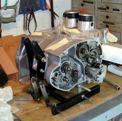
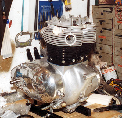
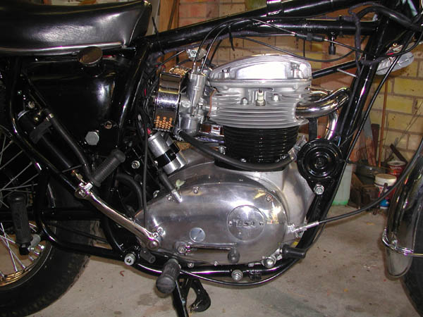
As said previously before I put the barrels on all the bits on either side of the motor have to be fitted. This includes the timing gear, the gear cluster & sprocket, the clutch chain wheel-main drive sprocket - primary chain assembly and then the alternator. I will discuss these as separate operations.
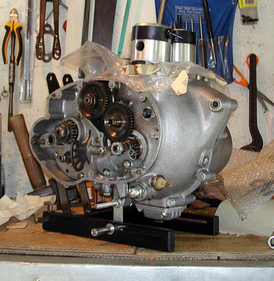
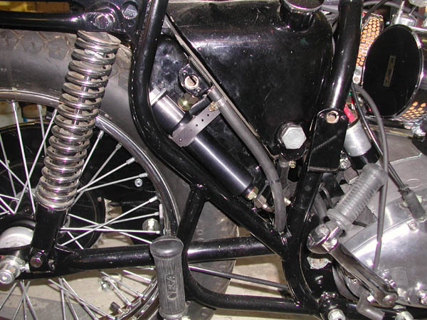
Note the SRM sump clearly visible
The timing gear is fitted and the camshaft turns freely and I have fitted the main crankshaft oil seal.
Every time I see that oil seal I wonder about how effective it could be when you consider how narrow
it is and how narrow the surface is in the casing that it presses into. There isn't even a lip to stop the
seal going in too far. It is as if it was added afterwards but really is essential to seal the crankcase.
Loctite Bearing Retainer is essential in the fitting of this seal.
The oil pump is a critical component on the engine and any deteriation in its operation can have
catastrophic results. I had already pulled it apart and cleaned it and reassembled it only to find that the
pump would not turn. This was because I had not put the cogs back exactly the way they came out.
Because of the very close tolerances needed to make the pump efficiently pump oil any change will
cause serious problems. Once I worked out the correct assembly it now turns OK. One thing I was told
to do was polish or grind the inside surface of the pump endplate. The cogs rub against this plate and
can wear grooves into the steel. This will allow oil to escape back and thus reduce the pumping
pressure.
Looking at the pump it is hard to believe that such a small component can do so much and can bring
the whole motor down if it fails. When I finally assembled the pump I used Loctite on the bolt threads
and tightened them and that horrible feeling again. The feeling of a bolt that is not tightening but
getting easier to turn. This was not a easy problem to solve as parts for a 1970 oil pump are just not
available. So after firing off a whole lot of emails to various parts suppliers asking about a spindle
housing, the negative answers started to dribble back. I could have bought a new pump with a cast iron
body but no spindle housing for my 1970 one. In the end Classic Fasteners came to my rescue with a
3/16" BSF Recoil thread repair kit. This was expensive but did the job and was a lot cheaper than a
new pump. Also if I have any trouble with the other three threads in the pump I can repair them also.
The next step was to fit the pump and I found that one of the studs was a bit chewed up where the
clevelock nut had damaged the thread. New studs were bought from British Spares at about $3 each.
The gasket that came from my gasket set needed some modification as the hole where the non-return
valve sits would have fouled the valve thus preventing it from working. This hole had to be enlarged
slightly. Another second rate reproduction part. The pump has now been fitted and bolted on with new
clevelock nuts. The torque setting of 7 ft lbs had to be guessed as my wrench only goes to 10ft lbs.
Some engine builders use allen head UNC bolts
instead of studs to hold the pump onto the engine. This makes fitting the pump a
lot easier although could lead to damaged alloy threads in the crankcase.
When I dis-assembled the bike I packed the gear cluster up in plastic and stored it for later inspection.
A couple of months ago I unpacked it and inspected it with my untrained eyes and noticed that the
dogs on two of the gears were worn and had been hand filed or ground. As I was concerned I took it to
a local bike mechanic who specialises in SR500 cafe‚ racer style machines. His opinion was that I
should try to replace them if possible.
British Spares listed the two gears in their price list at about $75 each but then I noticed in a Just Bikes
mag an advert for a complete gear cluster in very good condition for $250. In order to make up my
mind I had another look at my gears and noticed that many of the cogs had surface pitting where the
case hardening was failing. This suggested to me that the new cluster was the best way to go so I
contacted the owner in QLD and had it mailed down COD. The new cluster is not perfect but is a lot
better than my old one and will just require a couple of new bearings. These were ordered and just
arrived yesterday from British Spares.
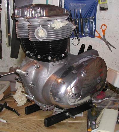
Note plastic sheeting to stop dirt getting into crankcase
Have fitted the new bearings and bolted the cluster into the case to check layshaft endfloat. Have ordered a new thrust washer from SRM to get the right float which should be just perceptible. I am having some trouble with the camplate / gear selector mechanism not moving freely enough once the cluster is installed in the casing. I need to replace the camplate plunger as my old one is heavily worn and the one I bought from British Spares doesn't fit (another Triumph part). So I wait for a parcel from SRM to arrive in the mail.
I now know why the camplate would not operate properly as I had installed it around the wrong way. It now works well but I still need that new plunger. Would like to replace the layshaft thrust washers but you can't replace everything.
2-8-03 The selector plate plunger has arrived now and I have fitted it and bolted the gear cluster in place. I also bought a new 20 tooth sprocket. My old 18 tooth Firebird sprocket was a little worn and I had been advised to replace it with a 20 tooth version as fitted to the Thunderbolt & Lightning. This will give better touring comfort (revs) at 100 kph and less vibration. I had thought that for a bike to ride around town the 18 toother might be a good solution but decided to go with the 20 tooth version. This sprocket appears to be a repro part and fits very well which is a pleasant change.
Although I had already fitted the oil pump I was not 100% happy about it as the gasket was a poor fit. Obviously a damaged or blown gasket on the pump could be a catastrophic situation with nil oil pressure being the result. The top oil holes did not line up and the hole where the ball valve fitted was too small and out of position. What is so difficult about making a gasket with holes in the correct place. Some of these reproduction part makers don't make much of an effort. I had modified the gasket with a wad punch but decided to buy a new one from SRM. I assumed that their gaskets would fit so I was very disappointed to find that their gasket was just as bad. I have now obtained some gasket material and today I made a new one using the old gasket as a pattern. I punched out the stud holes then fitted the gasket and pressed the gasket against the oil holes. This leaves an impression in the gasket material that you can then use as a guide to position your wad punch. Will leave the torquing of the three nuts to when I have the torque wrench reducing adapter made up. This is an adapter I have dreamed up to allow a 20 - 140 ft/lb wrench to tighten nuts to smaller settings such as 7 ft/lbs for the oil pump. I have tried to obtain an inch / lb wrench but they are hard to find. While I had the pump off I replaced the O ring that seals the spindle shaft.
8th August 03 - I have given up trying to find replacement fork sliders that will bolt up square with my front wheel spindle. I bought a 2nd hand left Triumph slider from British Spares at a cost of $80 only to find that it was very 2nd hand. There was extensive rust in the bore and I believe that by the time I clean the rust out the amount of metal lost will ensure that the bush to slider clearance will be excessive. Have a friend who is soaking the fork slider in molasses which he claims will clean off the rust. This is going to be interesting as I had never considered using molasses for such a purpose. He is also welding my engine lifting cradle frame and an adapter to convert a right hand torque wrench into a left hand version. Anyway I took my two sliders and spare front axle to my machinist to have then machined so that the clamps will bolt up square and I can then have a vertical wheel on the front of the bike. After listening to a number of suggested explanations as to why I have this problem with the forks I have come to the conclusion that none of them know what they are talking about. At times you just have to trust your own judgment and not listen to others.
The machined fork sliders are back now and the front forks are assembled and they look great. Now I can concentrate on finishing the engine.
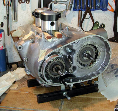
New 20 tooth sprocket fitted
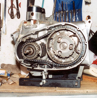
I have now fitted the clutch with the drive sprocket and primary chain and installed the alternator rotor and stator. Decided I would order an SRM alloy pressure plate and needle roller lift bearing. This involved the shortening of the clutch rod which was again done by my machinist as I needed to get a perfect flat end on the rod. When I fitted the inner timing cover I discover that there was .004" gap at the rear of the cover. When the rear bolts were tightened up to close the gap the kick start shaft would bind in the bearing. This meant that the cover was distorting as I tightened the screws. Off to the machinist again and hopefully I will have more luck this weekend with the timing side assembly. If all goes well I will complete the drive and timing side assembly and then ready to install the barrels.
After a couple of attempts at fitting the inner timing cover I finally completed the assembly and have both the left and right covers installed. I had to return the covers to my machinist for a second attempt as after tightening up the screws the crank would not turn. We discovered that a small amount of metal had to be removed from the cover around the outer bush that supports the idler gear.
Stainless Allen head bolts were used to mount the covers and Aero Grade Hylomar used to aid in achieving an oil tight joint.
At last I had reached the point where I could fit the barrels so I lined up a friend for a Saturday afternoon and after a little preparation positioning the ring gaps and installing the gasket we slid the barrels on. It all turned out to be so easy with that extra pair of hands. The cam followers were always a concern for me as they can easily fall into the crankcase while slipping on the barrels. Circlips are meant to be fitted to the top of each follower but the special tool to fit these circlips is not obtainable. Some re-builders use heavy grease to hold the cam followers in place while assembling. This grease will melt away after a period of running. I came up with another method to hold them in place. I cut four short lengths of clear plastic tube and inserted a piece of wire through each tube end. The tubes are then pushed over the ball end of the follower and the wires are twisted together and tied to a valve spring. Using the grease and the plastic tubes guaranteed a safe barrel installation.
The 12 point barrel nuts were fitted with Loctite and tightened up using the torque wrench extension I had made up from the diagram in the BSA factory manual. This motor was starting to look really great and I decided to continue with the fitting of the head.
 |
 |
 |
||
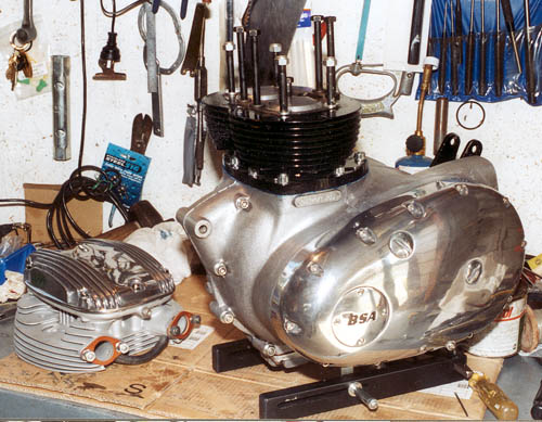
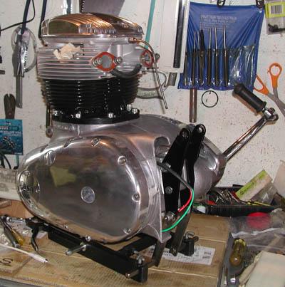
Side-covers on and then the barrels and head
At last I was making some progress and was able to fit the head with its new solid copper gasket and torque it down. Everything was going so well so I continued and started to install the valve gear but as so often happened I was short some part or other. In this case it was one of the thrust washers that fit either side of the centre rocker arms towers. About 12 months prior I had ordered some thrust washers but when they arrived the order was short one of the large diameter washers. Since then I had forgotten about the missing washer. So now I wait for the washer as it is holding up the most important event of all - The engine installation in the frame.
 |
 |
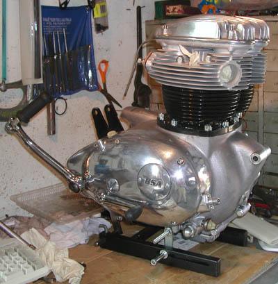 |
Engine with barrels and head installed
Well the thrust washer arrived and so the final assembly was completed but only after a small amount of anxiety. While trying to get one of the washers and spring washers into place they shot out and I heard one bounce across the garage floor. Fortunately the spring washer landed on the bench and I haven't found the thrust washer yet. However, I had a spare so in it went and the job was completed after tightening the rocker cover down.
If all goes well the motor will be in place in the frame by next week. My friend, Pete Armstrong, will give me a hand and I might see if I can get a third set of hands.
In the meanwhile I have obtained the paint from a local paint supplier in Bathurst (Auto West) and located a Ken Robinson of Oberon who is doing the spraying for me. Ken has a very nice collection of Ducatis as well as the odd M20 or Commando Roadster. His shed also has a number of project bikes ready for his retirement.
Have obtained some new petrol fittings and hose and once the engine is in place I can fit the Amal carbs and then look at making up the fuel lines. New lever action taps from a 1971 A65 are ready to be fitted and should ensure a fuel tight seal.
Last Monday with a friends help I managed to fit the engine into the frame. I had made up a lifting cradle supported on a pulley system which I was sure would make the job very easy. However this was not to be as once you get to the point of fitting the engine into the frame what you really need are a couple of extra helpers. After a lot of fiddling around and scratched paintwork we finally got it into place. I think the SRM sump made it more difficult as it hangs down further and catches on the frame.
The paintwork has been touched up and it sure looks a beautiful sight sitting there in my garage. Some other bits and pieces have now been added and it is all coming together very nicely.
Today was a very special day as a box arrived in the mail from Alternative Motorcycle Repair (AMR) in Tucson Arizona. The box contained part 82-9796 which is the bracket that fits under the fuel tank. I have been searching for this item for nearly 3 years and have tried every supplier I can find and searched the Web many times. About a month ago I decided I would have to find someone to fabricate the part for me but decided to give the Web one last try. The Google search engine came up with a match at AMR in Tucson although the part was listed with a zero price against it. This usually means that it is out of stock but I fired off an email anyway and to my surprise I got back a positive reply saying they had a used part for $15. That was good enough for me so I quickly accepted the offer and it arrived today.
Patience is one thing I have learned from this restoration over the past three years. As a result I believe I have avoided many mistakes and rough work that would have resulted from working to a tight timetable. It also helps to keep other parts of your life in the right perspective. Most of us have commitments and if we spend every waking moment in the garage our wives tend to get resentful and see the bike as a competitor.
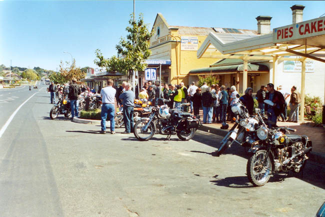
I have just spent the best Easter holidays for a long time. The weekend started on Good Friday with a visit to the classic bikes and riders who annually come to Bathurst for the week leading up to Easter. Each morning for that week they meet at Kelso near the caravan park before heading off for a ride around the district.
There was plenty of eye candy with bikes ranging from 1920 flat tank Triumphs and BSA's to modern BMW and the occasional 860 GT Ducati V twin. Saturday morning was especially rewarding as they all headed off together as one on their way to a round trip to Oberon and back. Next year will be my year as I am determined to be present at least for one of the rides.
The remainder of the weekend was very relaxing with plenty of time to get some of those little jobs done on the bike that contribute to its completion. It was a very rewarding time as I was able to see many things coming together and see the bike approach completion. Some of the areas worked on were:
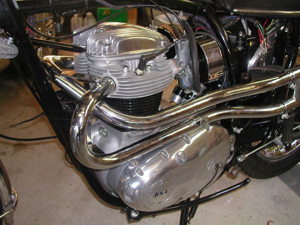
Trial fitting of exhaust pipes and mufflers which turned out fairly well but left a question about how to seal the pipes into the head as they were not a tight fit.
Installed the new chain and chain guard
Installed the new needle jets in the Amal Concentrics and cleaned up the flange facing using a sheet of glass and a sheet of emery paper.
Installed air control and throttle cables.
Installed oil filter into the tool kit area and connected up oil lines.
Installed fuel lines.
Test fitting of the sidecovers after new oddie studs were installed. I made up rubber washers to fit under the heads of the studs by punching out disks of rubber from a bike tube using two sizes of wad punches.
Spent quite a bit of time trying to work out the best routes for the carburettor cables. I studied previous photos of the bike as well as Bacon's "Restoring BSA Twins".
Connected up the cables to the coils and made up the spark plug leads.
I tried to respray my rear brake lever but in the end after a couple of less than acceptable results I decided to just get it powder coated in gloss black.
 |
 |
|
|
Right Side |
Left Side with pipes in place |
The following weekend gave me the opportunity to continue the push to get the bike completed.
In the course of the weekend it became plainly obvious that the front brake linings needed attention. I have now obtained a set of linings and rivets and hope to get the job done this coming weekend.
Adjusted handlebars and control levers.
Fitted Boyer Bransden rotor and stator to timing side and spent some time reading up on setting the timing. I am now fairly confident that I can set this correctly.
Adjusted the valve clearance and decided I really needed to replace the valve clearance adjuster screws and lock nuts.
Fitted the points wiring with a new grommet
Fitted the clutch cable and adjusted it and it seems to work. I had fitted a SRM alloy pressure plate and needle roller lift bearing. This involves chopping a bit off the clutch rod and I have been concerned that too much might have been removed by the my machinist. All seems well and i have now fitted the kick start lever and gearchange lever.
Tried to grease the speedo drive and front brake cam bearings but found it difficult to get enough pressure using the small push type grease gun.
 |
 |
|
|
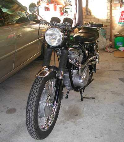
Front Shot |
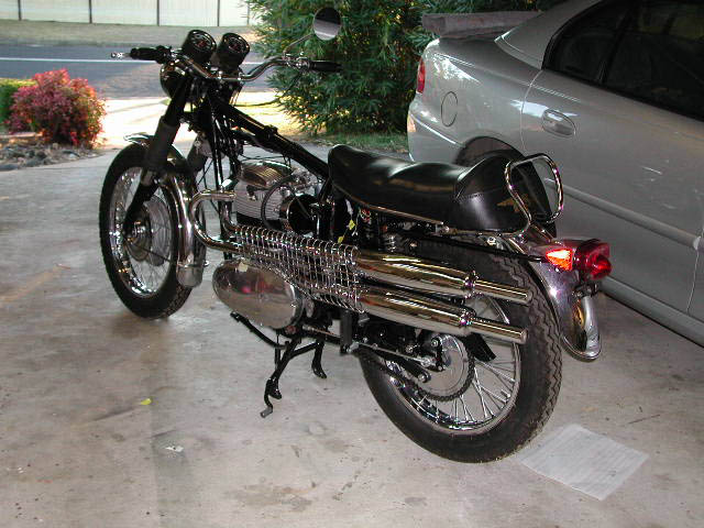
Left side showing the upswept pipes |
I now have the tank fitted along with the side-covers and the transfers are in place. All that remains is to fit light bulbs, new spark plugs, a couple of hose clamps to the valve gear oil line.
The problem over sealing the pipes into the head is now solved following a suggestion that I use some brass foil wrapped around the pipe. I was able to buy a packet of brass shim from Repco Auto Parts in Bathurst. This consists of a series of 6" square pieces of brass of varying thickness. I cut two strips of this material and fitted it inside the head port. The pipes were then pushed in and sealed onto the brass.
The best type of oil for A65 engines is a hot topic amongst the BSA community and many people have strong opinions on the matter. I have chosen a Shell Advance HD50 which is a SAE 50 grade with synthetic modifiers. Hopefully this will keep the main bearings happy.
 |
 |
|
|
Right rear view |
Oil filter installed into tool box |
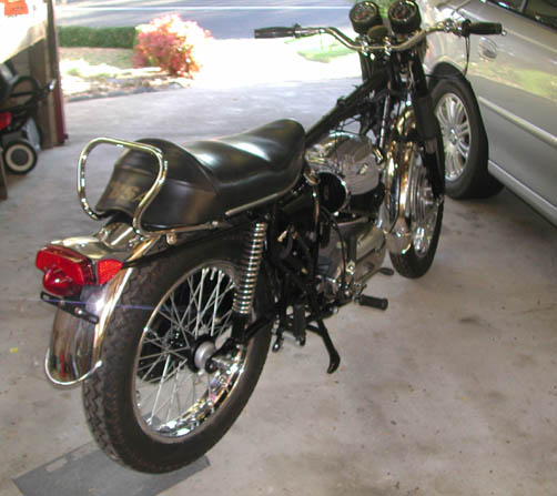
|
|
|
The finished job (trouble is it doesn't work)
|
After quite a delay I arranged with a friend, Peter, to have a go at getting the bike going. We filled the oil tank, the gearbox and primary chaincase and then tried to connect up the battery. Quite a few sparks and a couple of blown fuses later we decided that I had some work to do at tracing the wiring and isolating the problem.
I have spent some hours studying the wiring diagrams and have already found a couple of errors in the wiring. Why can't wiring diagrams look like the wiring harness.
Firstly I discovered that I had bought a battery with the terminals around the wrong way and as a result I had tried to wire up the bike as a negative earth. Next I had wired up the coils completely in reverse so that coil 1 was wired up as coil 2. After fixing these problems I cautiously touched the active lead to the battery and NO SPARKS.
The following weekend I decided to have a go at getting it going so poured some petrol into the tank and then discovered petrol running down the body of the fuel tap. I thought "this probably just needs a tightening of the nut on the tap" so I put the spanner on the nut and the tap fell off. It had snapped clean off - level with the bottom of the tank. After frantic efforts to catch the petrol pouring over my engine I then had to hose down the garage floor.
After some investigation I have discovered that these lever action taps, made in Taiwan, have a tendency to break about three threads from the top. This is because the inner surface is also threaded to take the screw in filter. The combination of an inner and outer thread weakens the alloy used in the taps considerably. Solution is not to over tighten and also screw the tap in as far as it will go so as to allow some of the stronger part of the tap to get a hold in the tank.
As I didn't want to waste the afternoon I decided to test out the electrics on the bike so after some fiddling I discovered
Headlight worked including park, low beam and high beam
Tail light works
Ammeter goes into discharge when the lights are on - very good
Horn gave one faint chirp followed by silence - at least I knew the wiring was correct
After some fiddling and then realising that the ignition must be on - the stop light worked using the foot pedal although the light flickered as the pedal was pressed further.
Couldn't get the front brake to work the stop light but after some testing I could tell that the wiring was correct as I had power on one wire and a circuit to earth through the rear bulb.
Decided I was going to need a new rear stop light switch and that the horn was dead. When I put the horn across the battery I got nothing from it.
The following weekend (14th August 2004) I fitted the new fuel tap, tacho lighting bulb and after some adjusting of the pedal movement discovered that the rear stop light switch was OK. I then removed the front brake cable which has a micro-switch built in to operate the stop light. When I disassembled the switch it was clear the metal contacts were not contacting. This was fixed by adding a couple of lumps of solder to the lower contacts so that they come into contact with the upper part of the switch when the brake lever is operated.
Now that I was flushed with the success of getting the lighting working I had more confidence that the engine would actually fire. I poured some more petrol into the tank and gave the kickstart a few cranks but nothing happened. I then held down the buttons on the carbs till they flooded and gave a few kicks and to my amazement it fired a couple of times. Another few kicks and I was able to get a few revs out of it. After having woken the neighbourhood from their afternoon sleep I turned it off to go in and tell the good news to my wife who didn't seem to appreciate how important an event this was.
Returned to the garage with a torch as I wanted to check that oil was returning to the tank. Fired it up again and discovered it ran better with the air control lever in the half raised position. Oil was returning to the tank via the oil filter and was a bit frothy (lots of fine air bubbles). I assume that this is due to the air in the return lines and the filter body. Will need to monitor this to ensure it doesn't continue. The oil light seems to be operating as it goes off when the motor starts and comes on again when the motor is turned off.
Next step is timing with a strobe light and then some adjustment of the carburettors. I have purchased a carburettor balancer which just indicates differences in air flow. This is a very simple device and is called Gunson's Carbalancer. I used a device similar to this many years ago when I had a Triumph Dolomite Sprint which was fitted with twin SU carbs. There is a good article on the AMR web site explaining initial carburettor adjustment. http://www.amr-of-tucson.com/idle_adj.html
It is now a few months later and a lot of water has passed under the bridge. I initially tried to tune the engine myself but was unable to get a satisfactory idle. I then took the bike to Tony McGrath a member of the Veteran & Vintage section of the Panorama MCC in Bathurst. He quickly picked up that there was a problem with the left hand carburettor. This turned out to be a blocked pilot jet so at last it was idling in a reasonable fashion. Tony was also able to confirm that the alternator was charging OK.
I was still not totally happy so with the help of a friend I balanced the carburettors with the Gunson's Carbalancer. This provided a steady idle but on closer inspection one throttle slide was higher than the other which was of some concern. Next time I started the bike it was idling very poorly and when I removed the right ignition lead and found it made no difference I realised the right pilot jet must be blocked. Once fixed the engine once more was idling well.
The easiest way to adjust each carburettor is to get the engine running and then disconnect a plug lead and then adjust the pilot air screw and idle speed on the other cylinder till you get the fastest idle with the least raising of the throttle slide. It is just a matter of then doing the same to the other cylinder. It is fairly easy with the engine just ticking over to match idle speed on each side as you can almost count the firing strokes. Once you connect up both plug leads it will be necessary to back the idle screws back about a 1/4 turn.
This truly a memorable experience and one I will remember for a while. I had not ridden since about 1982 and had spent the last 4 years restoring the bike so was a little concerned about this first ride. Rebuilding an engine from its basic components does give you an excellent understanding about how the thing works. However, its also means that you tend to have your ear cocked for any strange noises and naturally tend to think the worst.
As the bike is on Conditional Registration and classed as a Historic Vehicle I have to let the club registrar know when I am taking it out for testing and where and how I am going. This form of registration really limits you to club events and only costs $86 per year.
I started out after putting on all the clothing and was pleased that the gears appeared to work OK. The engine pulled strongly and all was well for about 4 kilometres when the engine started to misfire. At this point I decided to limp home and have a look at the problem.
An unfortunate problem but not bad for a first ride. On checking further I discovered the plugs were fouling and this appeared to be caused by a too rich mixture and too much lead replacement mixture.
Despite having the engine idling well the throttle slides were still at different heights and the mixture appeared way too rich. This concerned me greatly and after discussing the problem with Mark Adams at Great Western Motorcycles I decided to replace the carburettors. I was able to buy two new Amal Concentric 930 for $400 including freight from NZ. When they arrived the alloy was rather dull so a bit of buffing was required. Once fitted I attacked the tuning once more and this time the throttle slides were even.
I had booked the bike into Great Western Motorcycles at Kelso to get an expert to check it over. As it turned out Mark said I had got the balance very close. As they had just moved to new premises their dyno was not running so I arranged to bring the bike back in a couple of weeks to check the mixtures. The result was that Mark believes that the exhaust valve on number one cylinder is not sealing properly. Apparently valves can bed in so it might come good but there is a strong chance that I will have to remove the head to check it out. Mark also suspects that I need throttle slides with a smaller cutaway to cure a flat spot just off idle.
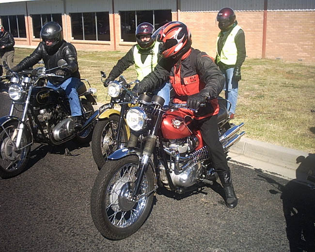
This Easter was the Vintage Motor Cycle Clubs annual Easter Rally "Tour of Bathurst" and I was fortunate to be able to take the bike on runs on Wednesday 23rd, Friday 25th and Saturday 26th March. The weather was perfect mostly with warm sunny days although the Wednesday looked like it might have been cold and wet until the sun broke through.
 |
 |
|
|
Morning Tea at Oberon |
Leaving on Saturday |
The bike performed very well over the course of the three runs with the only problems being a little clutch slip under full power acceleration and the tendency for the left throttle slide to stick just above idle and it felt a bit like cruise control. I have since fitted a new set of fibre plates and clutch springs and tested it today and it feels good
This has been a very rewarding project which has taken about three times longer than expected. However, I have learnt so much more as a result. To know the internal workings of the machine you ride with a high level of intimacy can be very rewarding. In my case it can also leads me to realise just how many things can go wrong in a British motorcycle engine. No wonder they leak oil when you consider the effect of two pistons going up and down together and how that changes crankcase volume. Yes I know the breather should deal with the changes in volume but I remain a little skeptical.
The bike has been restored to standard condition with a few small improvements:
7" Lucas headlight with QI bulb and ammeter as fitted to the Lightning in lieu of the tiny 5" unit
Extensive use of stainless UNF bolts with heads polished. Chrome bolts where cycle thread used
SRM alloy sump and magnetic drain plug
SRM alloy clutch pressure plate and needle roller lift bearing
Allen head sludge plug
High rise bars replaced with flat English style bars
20 tooth gearbox sprocket instead of the 18 tooth Firebird part.
Stainless Allen head bolts for engine sidecovers
Sealed wheel bearings
Lever action petrol taps
Hi-De-Hi oil filter kit - this uses the Trident cartridge and the whole fitting squeezes into the tool box area
The engine was not re-bored but was kept at its second re-bore size with new rings fitted. The bottom end was rebuilt with new standard mains and big-end shells. The crank didn't need grinding and a new sludge tube was fitted with allen head plug. Camshaft was replaced with a good 2nd hand unit and bushes replaced along with new cam followers. All seals and tab-washers were replaced and Aerograde Blue Hylomar was used to seal the crankcases. The valve guides were OK and the seats were ground as they had become slightly pocketed which restricts gas flow. The head was bead blasted and I was a little disappointed as I had not expected it to open up the pores of the alloy so much.
The SRM bottom end modification was considered but the high cost made it impossible. In addition I have heard of a number of problems with SRM's work so feel that a well setup standard crank with frequent oil changes and the right oil should be the answer. It should certainly do me for the mileage I will be covering.
I had thought the gear cluster to be in good condition but on closer inspection I found that some of the dogs were worn and the case hardening on the faces of the teeth was failing in places. Luckily I was able to locate a good second hand cluster in Queensland at a good price.
There was significant corrosion to both steel and alloy components where it wasn't covered by paint. As a result virtually every nut and bolt was replaced. Where they were hidden I used zinc plated bolts but where visible stainless and chromed were used. A lot of buffing with a series of polishing wheels produced some pleasing results on the engine.
The front forks caused me some grief as I discovered on assembly that the wheel leaned to the left at the top. I have since found out that this is not unusual as towards the end of the life of the company the quality control suffered in some areas of manufacture. To fix the problem I had an engineer machine the clamps on the fork sliders so that they were square to the slider.
Access to a dealer with such a good supply of reasonably priced parts like British Spares meant that where ever a part looked a little second hand I replaced it. Other hard to get parts were sent away for plating or in some cases British Only came to the rescue. I found that they had a very good stock of genuine parts and many hard to get items although very expensive.
So far the engine has proved fairly oil tight although early on there were some drips coming from various places. Wet sumping seems to be a universal problem and although I was very careful when fitting the oil pump and the ball valve the oil will drop in the tank over a few weeks. It is a manageable problem and providing I run the bike every few weeks it is OK.
After some tuning problems I found that the carburettors were worn and it was necessary to replace them with new ones from British Spares.
|
A very rewarding and successful project and I have learnt so much about these engines. I am sure that I exceeded my budget of $10,000 by a long way but had little choice when a part was needed. One day I might add up all those invoices and see what it comes to. Certainly cost a lot for a bike that was supposed to have only done 5,000 miles |