4W FM Transmitter
TECHNICAL
CHARACTERISTICS:
Stabilised tendency of
catering: Vcc=12~16V
Frequency of emission:
88~108MHz
Consumption: 100~400mA
Sorry for that folks.
The original text was in Greek and it did made sense back then. The text in the
above web-link was translated to English using a PC translation utility, which
doesn't understand electronics terms such as Ohm and Farad. ![]()
As a result the reading and understanding of the text is rather difficult.
Anyway, mF = uF and MW = MOhm.
As for L2, take a 1MOhm/0.25W resistor, and wrap a few turns of 0.5mm (or so)
wire on it.
Play with the values if you are not satisfied with the results.
After all these projects are there for you, to experiment and learn.
Kyriakos
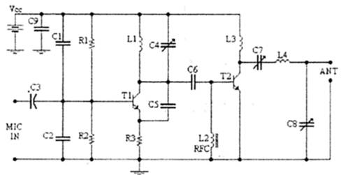
Materially:
The resistors are 1/4W.
|
R1, R2 |
10K Ohm |
|
R3 |
47 Ohm |
|
C1, C2 |
1nF |
|
C3 |
4,7uF/16V |
|
C4, C7, C8 |
0~45pF
trimmer |
|
C5, C6 |
10pF |
|
C9 |
100nF |
|
L1 |
4 turns, 7mm
diameter * |
|
L3 |
3 turns, 7mm
diameter * |
|
L4 |
5 turns, 7mm
diameter * |
|
L2 |
RFC
(resistance 1MOhm wrap around it a inductor of enough [many as you can] turns
of fine insulated wire.) |
|
T1, T2 |
2N2219 |
|
ANT |
Simple dipole
l/2. |
|
MIC IN |
Microphone
dynamic or other type. (It can also connected to a cassette player unit) |
* The inductors are air
form wire from coaxial 75ohm or other 1mm roughly.
Regulations:
With the C4 we regulate the frequency (set the frequency
for transmission).
With their C7, C8 we adapt the resistance of
aerial (practically to we regulate so that our voice is heard in the radio as
long as you become cleaner).
Notes: The T2 wants Heatsink
Tips:
Hi
Your Walkman is OK and so is the wire for your coils, but L2 should be many
turns of fine enamelled wire. Instead, wrap your 0.7mm wire around a 1M, 2W
resistor, tightly and one end to the other.
How many volts is your regulated (stabilized) power supply for this project?
Can it supply 400mA?
As MP said earlier, "mW" is lacking on the spec's for the 2N2222.
Which means that it is too small to get rid of its heat and will burn-out! I
figure that a 16V power supply will put about 8.7V across Q1 and about 155mA
through it. That is 1350mW. Even the recommended 2N2219 for Q1 will burn-out
without a heatsink!
Speaking of heating, with a 16V supply, R3 will have 7.3V across it and 155mA
through it. That's 1130mW, and the 1/4W resistor that is recommended will also
burn-out! Use a 47 ohm resistor that is rated at 2W.
If you use a 12V power supply, Q1 will dissipate 756mW. Still too much heat for
a 2N2222, but near the limit of a 2N2219 without a heatsink.
Didn't you use a heatsinked 2N2219 for Q2? When the circuit works properly, it
will get very hot.
You can still use a 2N2222 for Q1 if you use no more than a 15V power supply
and change R3 to 120 ohms, 1W. Then the project won't give 4W of output, but
probably only 1.5W.
A good test to see if the transistors are working is to feel their heat. Q1 and
R3 should always be hot, and Q2 will heat-up only if Q1 is oscillating.
Hi
That's great that you got it
working. Yeah, broken capacitors don't work very well.
It will transmit much further if you use about 15 turns or more for L2. Use a
1M resistor that is big enough for that amount of your 0.2mm wire.
With your 12V battery it won't have 4W of output, probably only 1W. Therefore
leave R3 as a 47 ohm 1/4W resistor, it should be warm but not hot. T1 and T2
should be very warm. Can you measure how much current that the project draws
from your battery?
It will be very difficult for you to tune C7 and C8 for maximum output without
a signal strength meter, a helper and walkie-talkies. It should transmit a
couple of kilometers. Can your helper scream that far?