Chance Vought F4U Corsair |
by Louis Dionne [[email protected]]
Based on an original design from Papy Kilowatt
February 2009.
[Last edit: March 2009]
Content:
- F4U Corsair Development
- Specifications
- Equipment
- Kit Contents
- Materials
- Assembly
Wings
Ailerons
Fuselage
Hatch
Stabilizer
Fin & Rudder - Completion
Light Spackling
Wing Fillets
Paint
Decals
Motor
Canopy - Trimming and Flying
- More Photos
F4U Corsair Development:
Originating in a 1938 Navy spec, when the need to replace the F2A and F4F could already be foreseen, the Vought Corsair was designed around an engine that also didn't exist yet: the Pratt & Whitney R-2800 Double Wasp, a monster 18 cylinder double radial, eventually capable of 2250 horsepower. (During the Corsair's development, corporate reorganizations brought the Vought company into Vought-Sikorsky and then Chance Vought, all part of United Aircraft, along with Pratt & Whitney and Hamilton Standard.)
The huge engine dictated much of the plane's design. Such a powerplant needed a comparably big propeller to absorb all that horsepower. Thus the 13' 4" diameter Hamilton Standard prop, the largest fittest to a fighter at that time. The Corsair's fuselage had to be high in the air, to give the prop clearance, But ordinary, straight wings at that height would have implied long (and weak) landing gear. The distinctive bent wings were developed to permit a reasonably short undercarriage.
The XF4U first flew in May 1940, and in October flew faster than 400 MPH, a record for a production fighter. A major re-design pushed the cockpit back 32 inches, which resulted in poor forward vision for the pilot, at least on take-off and landing. Development continued into 1942, when Vought delivered the first production F4U-1 to the Navy, which didn't like what it saw, especially when compared to the easier-handling, and very capable F6F Hellcat. The F4U had dangerous stall behavior, had tendency to yaw suddenly when landing, and, worst off all, bounced when it hit the deck. For use on carriers, these problems caused the Navy to insist that they be fixed, while it went ahead equipping with the Hellcat.
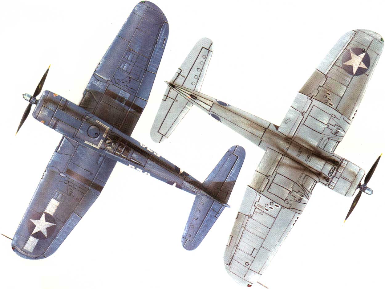
But the Marines, operating from land bases in the Solomons, needed capable new fighters to replace their aging F4F Wildcats. By late 1942, the first USMC squadron, VMF-124, took delivery of the Corsair F4U-1. In early 1943, they began to see combat, and were a huge success - with speed, maneuverability, firepower, and ability to absorb battle damage. By the summer of 1943, most of the Marine fighting squadrons had transitioned to the F4U-1, the first operational model, fitted with a distinctive "birdcage" canopy, as shown in the detail of a plane flown by Ed Olander (number 576). Boyington's squadron, VMF-214, switched over to Corsairs before they started their September 1943 combat tour.Based on combat experience, Vought improved the next version, the F4U-1A:
- a better visibility bubble-top canopy. The different canopy tops show clearly in the illustrations.
- a more powerful engine, the R-2800-8W. Equipped with water-injection, this engine could achieve 2,250 horsepower for brief periods.
- a spoiler on outside edge of right wing
- a longer tail wheel leg
Specifications:
Full Size
Wing Span: 12.5m [41']
Length: 10.1m [33' 4"]
Height: 4.90m [16' 1"]
Wing Area: 29.17m2 [314 ft²]
Weight: 6.300kg
Speed: 718km/h @ 5,500 m [446 mph]
Range: 1634km [1015 mi]
Max. Elevation: 11,200m
Engine: Powerplant: 1× Pratt & Whitney R-2800-8W radial engine, 2,250 hp (1,678 kW)
Armament: 6× 0.50 in (12.7 mm) M2 Browning machine guns
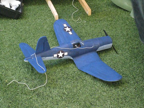
The prototype after the very successful test flight
Prototype
Scale: 1/16 eme
Wing Span: 630mm [25"]
Weight: 170-260gr [6-9oz], (206gr [7.2oz] on prototype)
Profile: S3021, 2° washout at tip
Wing Area: xx sq.cm [xx sq.in.]
Wing Loading: x oz/sq.ft (on prototype)
CG: 40mm from LE
Motor: CD-ROM
Propellor: GWS HD 7x3.5
Power source: 3S 500mAh Li-Po
Current: 5A
Prototype has 2 sub-micro servo driving elevator,
rudder and 2 more servo for the ailerons and no landing gear.
For indoor flight best to keep the weight under 7.5oz.
Equipment:
| Motor |
50-80W motor |
| Prop | Prototype: GWS HD 7x3.5 prop |
| Battery |
460 to 1000mAh Li-Po packs |
| ESC |
10A ESC Prototype: Castle Creation Phoenix 10 BL controller |
| Servos |
2-4 µservos, 3g to 9g Prototype: 2x 3.3g servos (rudder/elevator), 2x 3.3g servos (in each wing driving directly the ailerons) Recommended: 3x 3-4gr servos (ailerons, elevator) |
| Receiver |
µ receiver, 4 to 6 ch. Prototype: Sombra Labs Lepton 6 |
Kit Contents:
Kit consists of:
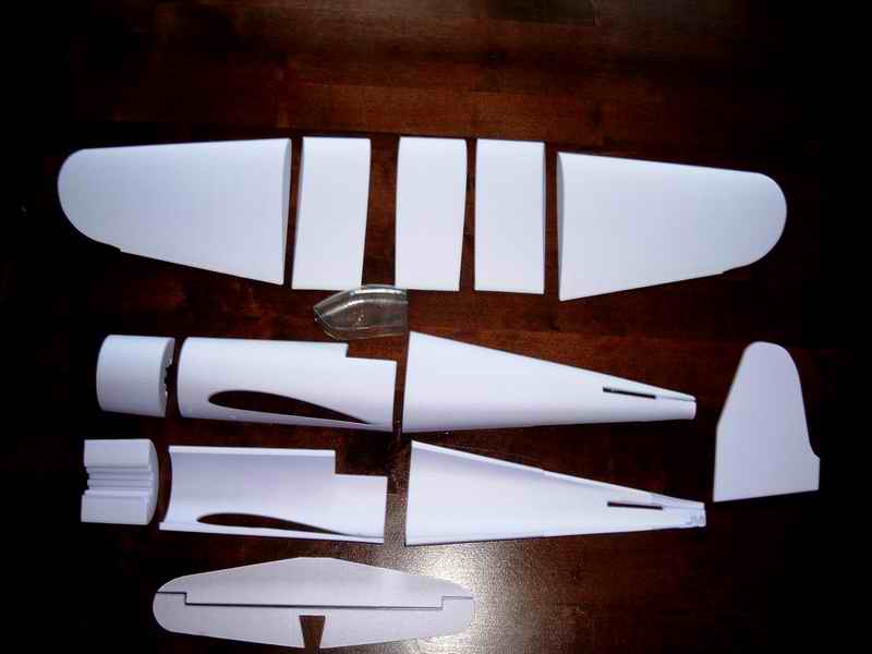
- All CNC foam parts to assemble the fuselaage (3 sections), tail feathers and
wings.
Fuselage is an empty shell of foam.
Wing, stab, fin slots and cockpit are already cut in the fuselage parts.
- Clear vacu-formed canopy
- Instruction CD with lots of pictures.
>
- Decal sheet with US markings
Materials:
Extruded polystyrene for the wings and tail feathers then
expanded polystyrene for the fuselage.
Glue:
- Water based contact glue (Latex)
- Carpenter's water based glue
- Foam friendly CA
Paint:
- Water based paint like acrylics applied with brush or small foam roller or sprayed with air-brush system.
- Foam friendly spray cans (Acrylics, Krylon H2O)
Hardware:
- Thin music wire (1/32")
- Carbon rods for the pushrods (0.040"), for the optional landing gear (0.070")
- Strong magnets to hold shut the fuselage hatch (1/8")
- 1/32" PCB material to make the control horns and tail wheel bearing plate.
- Main wheels, like the Du-Bro 1.25" Lite Wheels (Du-Bro part at Zebra Hobbies; #125MW ), optional
- Tail Wheel (Du-Bro part at Zebra Hobbies; #12MTW), optional
- 3M Blenderm for hinges; good adhesion, waterproof, thin and very flexible.
- Masking tape; reinforcement
Decals:
- Make you won on your ink-jet printer on regular paper and glue them on
- Printed on an ink-jet printer on Avery Clear Full Sheet Labels (Avery #08665)
- Here is something to work with:
| Assembly |
| 1) Wings |
|
Wings are cut from pink extruded foam in 5 panels. 2 outer panels with a positive dihedral, 2 inside panels with negative dihedral and one central panel mostly inside the fuselage. The wing tips are already cut to shape.
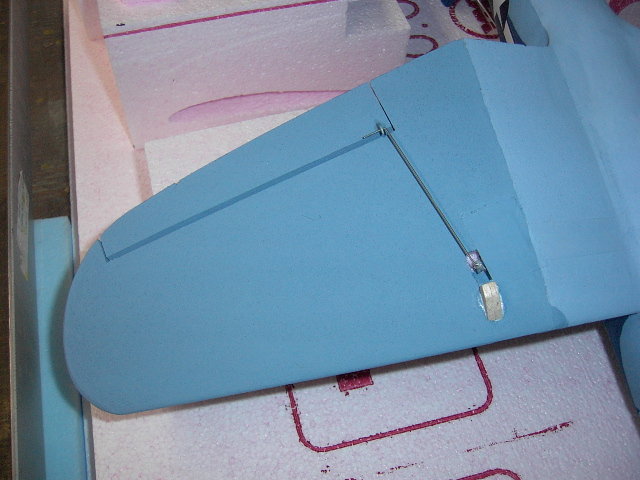
I propose to use here 2 sub-micro servos (3-4gr) embedded in the outer wing panels to drive directly the ailerons. The 3.3gr servos I used were thinner than the wings. I dug the servo bays using a Dremel tool with a plunger for fixed depth. There is an alternate method to drive a single aileron from a single aileron servo. There is enough control using a single aileron on one side, but you need to provide more down travel than up. This technique has been used successfully by others, but I never tried it. I used 3M Blenderm to fix the ailerons to the wings, then painted over the tape. Acrylics are fairly flexible and stick well to the 3M Blenderm. Others have used light iron on covering like the Nelson Lite.
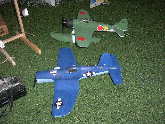
I hinged the ailerons at the top and dug a hole for each servo underside each outer wing panel. I would recommend installing the wing servos closer to the wing tips to reduce chances of damage to the servos if landing on the wing bottom. Mine are too close to the ground and I added a balsa bumper to prevent the servo arms from getting caught in the artificial grass at our indoor flying field (triple soccer field).
|
| 3) Fuselage |
|
The fuselage comes in 3 sections; the cowling, the main section and the tail section. Each section comes in halves. The cockpit and wing openings is already cut and part of the main section. The foam used for the fuselage is a heavier grade of Expanded Polystyrene. The Expanded foam has no residual internal stresses and gives excellent results for thin walled parts coming out straight.
The cowling section has is wide enough to have almost any motor in there. I made a round bulkhead to match the inside of the cowling. Added a few holes to allow for the cables and air to go through and positioned the bulkhead to get the prop where I wanted and glued the bulkhead in place making sure it was not skewed. The tail section has slot in the top and bottom for the fin, there is another clot for the stabilizer and elevators. All these slots are pre-made. You will have to enlarge the side slots to clear the 1/8" dowel.
The last section of the fuselage has slots for the fin and stabilizer. The next section describes them. Once interlocked and into the slots, you will glue in a few extra pieces of foam and shaping to complete the tail.
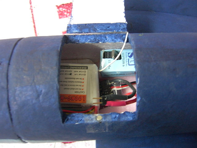
In order to service the plane and change battery a hatch is cut in the main fuselage section. The hatch on the prototype is 30mm from the cowling and has 40mm in length. It is 15mm deep from the top. The hatch is hinged on one side and is retained closed with 2 magnets, embedded in the hatch cover and the thickness of the fuselage side. The magnets prevent the positive air pressure from the turning propeller to push the hatch open. In the picture below we see the 1/8" at the bottom of the picture and inside we see the Loong Li-Po pack and beside it, the diminutive speed controller and finally at the top we see the Lepton 6. The balsa board wedged between the wing and the bulkhead and seating the flight pack can be partially seen above the pack in the next photo.
|
| 5) Stabilizer |
The stabilizer and elevators come in two separate pieces and are cut out of the same material as the wing panels.
-
Round the LE of the stabilizer using a sanding block.
-
For the looks, you may want to taper the TE, but this will weaken the foam in case of a sudden contact with Terra Firma.
-
Bevel the front of the elevators.
-
Separate the elevator halves cut a slot at the LE for the 1/8" hardwood joiner
-
Join the elevators halves using a 1/8" hardwood dowel.
-
Hinge the elevators to the stabilizer
| 6) Fin & Rudder |
|
| Completion |
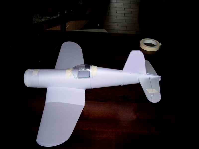
You can attach the wings to the fuselage in different fashions, but I recommend to glue the wing permanently in place as the lightest and strongest option.
The Tail Feathers
- Glue the stab and the fin to the fuselage slots at the rear, making sure everything is square.
- The last section of the fuselage ending past the tail feathers is built up using scrap pieces of foam.
- Use light sparkle to fill any hole left and smooth out everything.
Hardware
- Make yourself a few control horns (using credit cards, thin 1/32" PCB or thin plywood) and glue them to the elevator and rudder if installed.
- You can use .040" carbon rods for pushrods ending with a thin music wire glued to the pushrod using a wrap of Kevlar thread and CA.
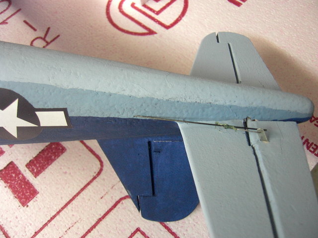
- I added a pushrod guide for the rudder and elevator pushrods to prevent flexing under load. These are made of 1/32" PCB material with a hole big enough for the rod to slide in. They are inserted in the fuselage side after making a thin incision at the right location with an X-Acto blade and then glued to the inside of the fuselage
- Use masking tape to protect your aileron servos and then use foam friendly glue to fix them to the fuselage sides and in the wing slot.
- Install your rudder and elevator servos in the fuselage. Set the servo neutral points and route the carbon rods through the fuselage sides and pushrod guides where appropriate to reach the servo and minimize the binding in the pushrods. A stiff music wire is used to drill holes through the fuselage where the pushrods will pass.
To take off from the ground, I prefer to have rudder for ground control and of course, landing gears. If you install rudder and landing gears, add a small tail wheel to a tail bracket glued to a slot cut half way through the rudder. End the top of the tail bracket in the rudder in an inverted L shape to transfer torque from the rudder to the tail wheel. A small piece of 1/32" PCB material is used as a bearing for the tail wheel. Use Vaseline to prevent the tail wheel strut from sticking to the bearing plate when you glue the bearing plate to the fuselage.
You can locate the landing gear legs at the wing bends. The landing gear can be made of a 0.070 carbon rod or stiff wire and thin music wire bent at 90degree as wheel axel. Fix the wire using Kevlar thread and CA. The carbon rod is then glued to a hardwood based imbedded and glued in the wings to the bottom of the wing. Use light weight wheels. I prefer to use the Du-bro 1-1/4" Mini Lite Wheels (#125MW). They weigh 1.1gr each.
| 1) Light Spackling |
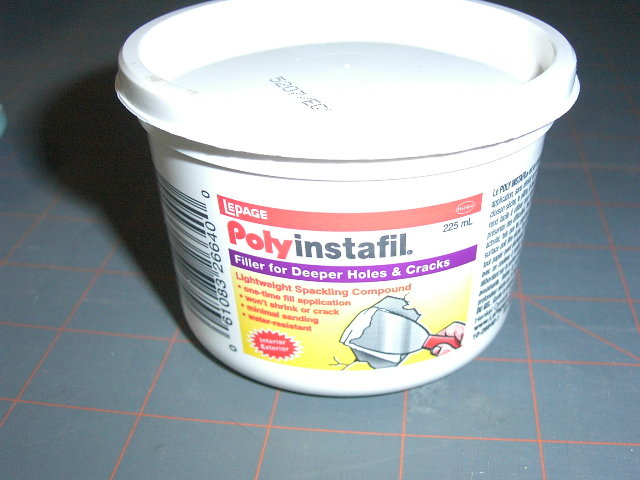
Use light sparkle to fill all the tiny foam holes and sand smooth. Cover the whole fuselage, let dry, then sand lightly. I use a Lepage brand from the local hardware store; light and far less costly then the hobby version.
| 2) Wing Fillets |
- Sand the wing seat to match the wings.
- Glue the wings to the fuselage
- Do the wing fillets between the fuselage and the wings using light spackle and a finger to smooth the fillet and minimize the sanding.
- Once sparkle compound is dry, sand carefully with sand paper rolled on your finger.
- Apply more sparkle to complete a nice fillet. Sand again.
This will produce very nice fillets, but they are somewhat fragile. You will need to put a few layers of protective polyurethane on top.
| 3) Paint |
- After the light spackle and the sanding,
- Apply Japanese paper tissue using polyurethane floor varnish (PUV), like Varathane, or diluted white glue to cover the fuselage.
- Add PUV coats to provide a harder shell to the foam.
- Sand smooth between each PUV coat.
-
For paint, I use cheap acrylic from the dollar store.
-
Either spray paint (thin with water) or brush a couple of layers starting with the light colors first.
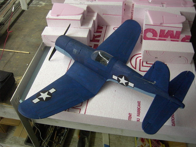
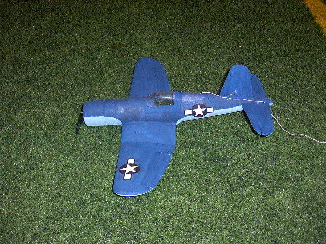
Once the PUV, Japanese tissu and base color paint job is done, complete with your favorite camouflage scheme. The Corsair has seen many countries and colors. An airbrush system can speed up the process, or smooth the application but a good old brush in a steady hand and patience can deliver fine results.
| 4) Decals |
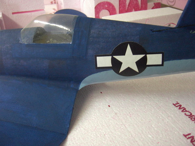
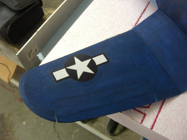
Add your decals.
You can use the plate I did : US Markings
Or make your own.
For
indoor use, you can print on white paper and glue the
markings using Stick-iT stick type glue or PUV to attach
the markings to the plane.
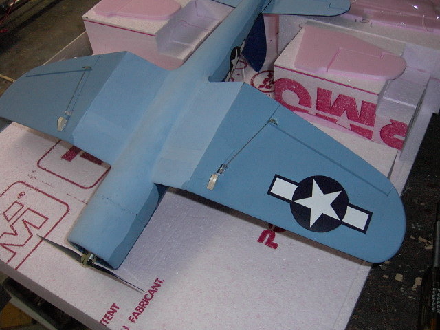
The completed the tail sections with the pushrods hooked up.
| 5) Motor |
The motor used in the prototype comes from a PC CD-ROM/DVD drive. My motor has a 29mm bell. The stator was rewound, magnets replaced by strong neodymium magnets. I machined a bearing motor holder and plate. The motor draws a bit over 5A with a 7x3.5 GWS HD propeller on a 3S Li-Po 500mAh pack.
This motor is fairly heavy and one can surely find a much lighter motor, like
-
Flight Park 250 (55W, 14gr, 2200Kv)
-
C2024 Micro brushless Outrunner 1600kv (17g) found at Hobby King.
-
Turnigy 28-22-CQ 1400Kv Brushless Outrunner at Hobby King.
Note that the use of a lighter motor will shift the weights and one will need to explore with the correct locations of the flight battery, servos and receiver.
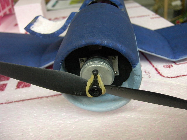
The firewall has holes above and below to route the motor wires and some air. The firewall was glued at the appropriate distance to provide the right clearance between the cowling and the propeller.
| 6) Canopy |
I made a foam plug for my Rufe and realized it would fit perfectly for the canopy of this F4U Corsair. This kit is therefore provided with the long canopy of the Rufe. The front section need to be cut and trimmed in small steps to make sure you will not trim too much.
My vacuu-forming machine is a simple wooden box with a top drilled with many small holes and another hole on a side panel to insert the tube of a shop vac. I make a plastic holder made out of plywood. I staple a rectangle of plastic material to the plywood frame and heat up the plastic over the heat of a stove burner. Once everything is soggy, turn the shop vac on and apply over the plug.
For the small number of kits I made, the canopy is provided and you will need to cut along the pencil marked line on the canopy and adjust for the sanded shape of your foam fuselage and cockpit section. I masked off the window areas of the canopy using left-over material from the decal print job (Avery #08665). The canopy was pressed against the foam once located and then the foam was sliced at the imprint left to slide in the canopy; so the canopy is actually lightly inserted into the foam. Use the picture below to paint the cockpit structure once glued to the fuselage section. Use the water based contact glue to hold the canopy to the foam. Paint is done outside the canopy to fill voids and such. A few touch-ups on the camouflage was done after the paint has dried and the masking removed.
In the picture above I still have to mask the canopy and paint the frame.
You may want to paint the foam inside of the cockpit black and add a pilot to your cockpit. I typically print 2 pictures of a pilot on my color printer; a normal and then a flipped image and then glue back to back to get a double sided flat pilot. Very light.
| Trimming and Flying |
- CG : 40mm from LE at root.
- Position the Li-Po pack inside the fuselage hatch along with the receiver and connect all the cables. Adjust their position to get the correct CG.
- Deflection of the elevator set from 6 to 10 mm.
- Deflection of the ailerons to 30° or even more to get quick rotation on the rolls.
- I used a GWS HD 7x3.5 prop on a 3mm shaft retained to the shaft with with rubber bands.
| Color Schemes |
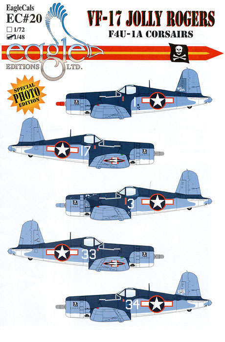
The F4U Corsair has seen many theatres and countries. There is a good selection of color scheme and markings to choose from.
Here are a few interesting color schemes:
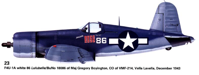
Mjr Gregory "Papy" Boyington of the VMC 214
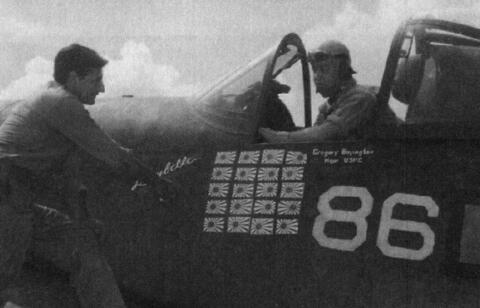
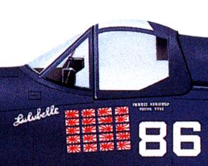
There is a controversy as to the name of this plane used for the photo shoot; some believe that the actual name was Lucybelle from his mistress at the time who apparently left him soon after with 15,000$ from Papy.
More information on F4U
http://aviacherteg.narod.ru/avia/Drawings/WWII/WWII_USA/F4U/F4U_AiK/F4U_AiK.htm
http://aviacherteg.narod.ru/avia/Drawings/WWII/WWII_USA/F4U/F4U_OSPREY/F4U_OSPR.htm
http://aviacherteg.narod.ru/avia/Drawings/WWII/WWII_USA/F4U/F4U_MK/F4U_MK.htm
http://aviacherteg.narod.ru/avia/Drawings/WWII/WWII_USA/F4U/F4U_ATL/F4U_ATL.htm
http://aviacherteg.narod.ru/avia/Drawings/WWII/WWII_USA/F4U/F4U_HAA/F4U1D_HAA.htm
| More Pictures |
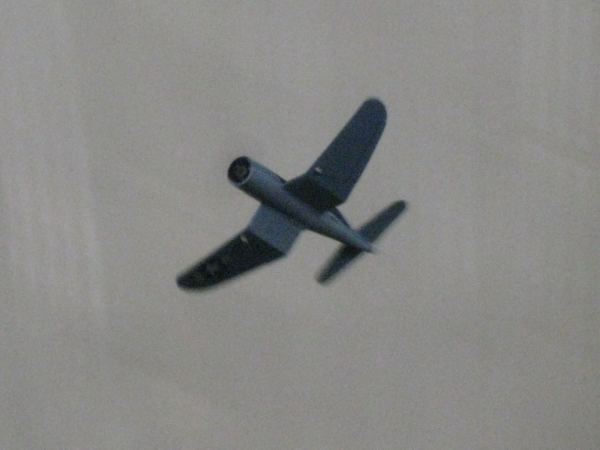
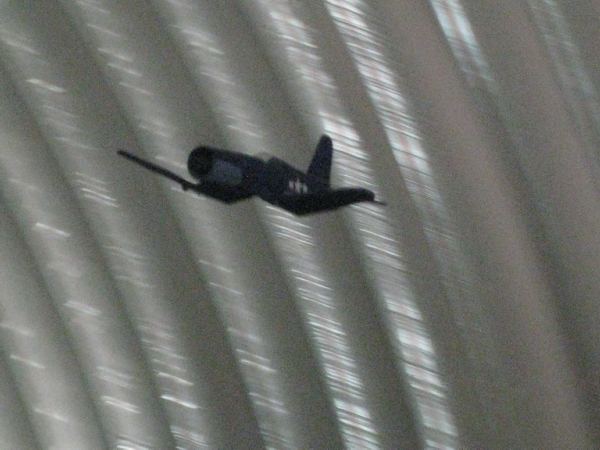
Pictures of the prototype in flight