The Central Pedestal has been modeled after a Boeing 737-500/600/700/800. I originally planned to model the entire cockpit after a 737, but this plane was not the plane I was most interested in, which is the Dash 8. I am thinking of changing the pedestal to model a Dash 8. The pedestal was made in the summer of 2002 with the help of Simpits.org (go straight to the Boeing 737 plans) and Chris Benton from the East Point Military Museum. It is made entirely out of MDF wood with the printed images from Simpits.org. At the local hardware store they cut the pieces to size, and once back home the building began. Assembling everything went fairly fast, and the next day I was already spray painting the separate finished parts. I used a generic dark gray paint, which turned out to be pretty close to the Boeing gray color. After this I bolted the four parts together, and taped on the decals. These decals are still on today due to the fact that it is very hard to get the instruments here and the lack of money. I also screwed the cup holder on, and put in my PFC single engine throttle in a special way (see pictures). In addition, I also made a spoiler lever with the pot meter that I had left over from my CH yoke. (the PFC throttle replaces the CH yoke throttle electronically).
The yoke was made during Christmas 2002. I had just moved, and set my computer up in a new way. At this time I also decided to make numerous changes to my cockpit. To start off, I was going to make a more realistic yoke. I had seen people put the entire CH yoke on top of a pole without the pole being able to move. This wasn't what I was looking for though. I made some drawings on my computer, and soon I had the plans seen below.
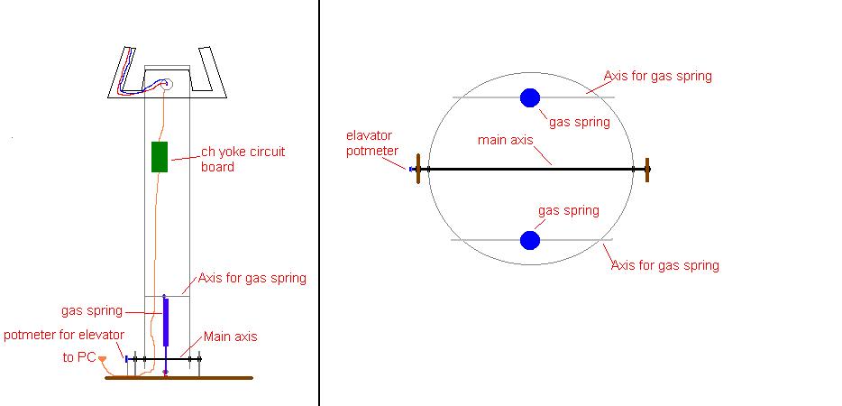
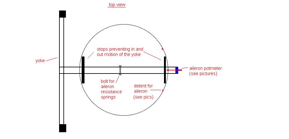
The construction itself is very simple. The main column is a water drainage tube with a diameter of 70mm, bought in a local hardware store. I cut the tube to a length of 1.85 meters, and drilled holes near the top for the CH yoke, and on the bottom for the axel providing elevator movement. I left All the hardware such as the small circuit board dangle inside the column. CH used shrink wrapping, which made the cables strong enough to let the circuit board dangle from them. I put the yoke into the tube, and made detents for aileron movement, which also avoided that the yoke would move in and out of the tube. On the bottom of the yoke, there are two gas springs inside for the resistance, plus the nuts can be adjusted to obtain the right resistance. Note that this yoke will not move back to its center position if released. The pot meter is connected to the moving axel through gears. Without the gears, the pot meter would not move enough distance, making it very hard for windows to calibrate it. The floorboard is 70X90CM which will avoid the yoke from toppling over. The cables just come out of the bottom of the column.
This is the first piece of hardware that I am pretty proud of. I am still adding switches to the twelve that I already have (Building started late December 2002). The main background picture is a picture of the PSS Dash 8 overhead panel blown up several times. I printed it out on 12 pages, and glued them on to a 50X70CM board with wood glue. When it came to the switches I needed to find a cheap way to make it work with the pc. I do not have the money for an epic card, and I heard about FSbus too late. I had already started to modify the switches according to the way Rich Anderson had described. This way does work pretty good though. I took apart a very old keyboard until I was left with only the circuit board, which is a very small thing. I will solder the wires to the board and the switches when all switches have been placed.