PIC Clock
|
PIC Projects More projects will follow |
|
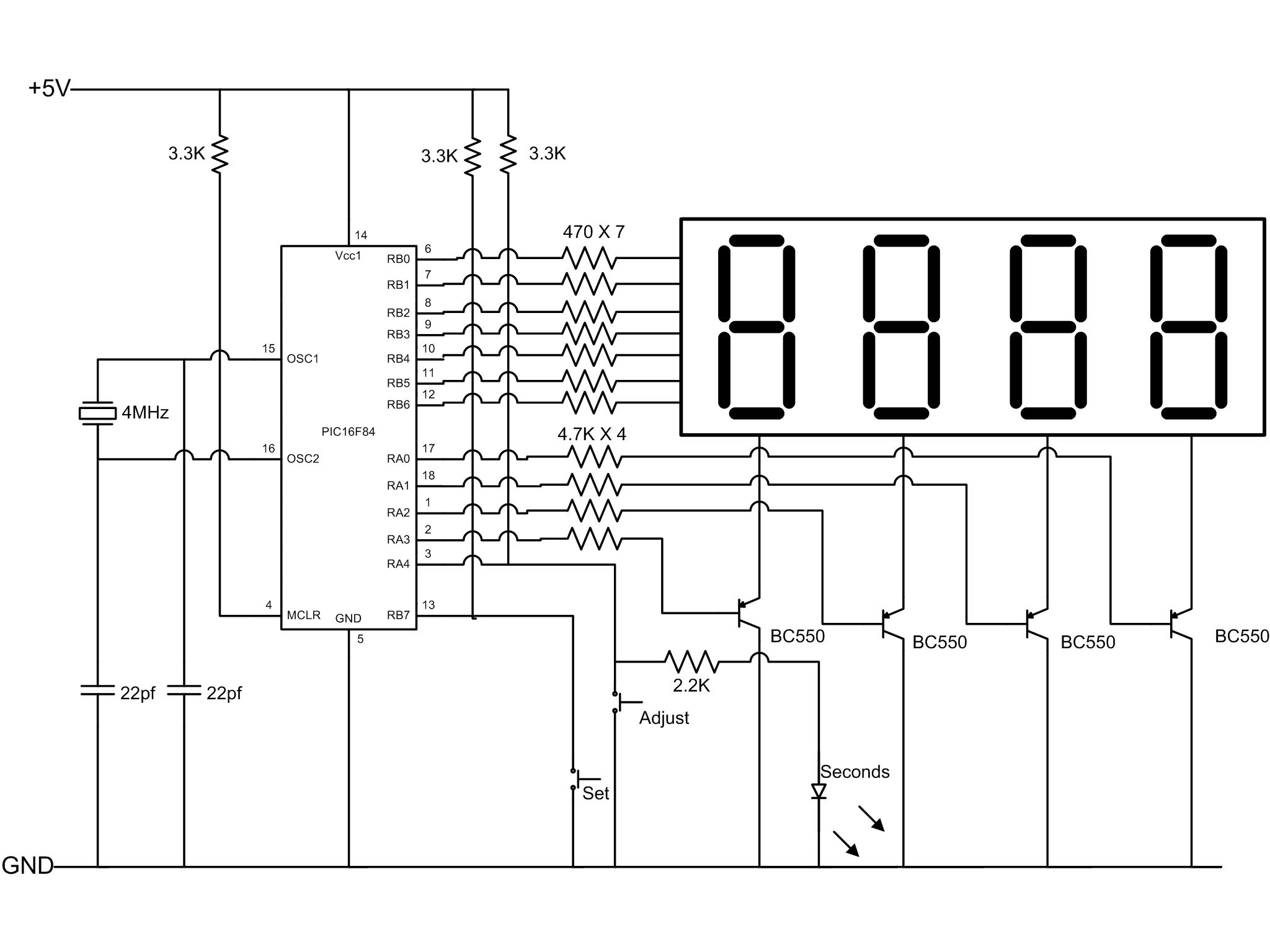
Here's the schematic of my PIC clock project based on PIC 16F84 microcontroller. Click diagram to get a larger version of it. on It uses a set of 7 segment displays driven from Port B. 4 NPN transistors (BC550) are used as the switches. Crystal oscillator used is a 4MHz and the clock timing is by using the pre-scale, timer 0 and software delay.
Pre-scale is set to 16, timer is loaded with 125 and the rest is by a software counter. timer0 overflow generates an interrupt which triggers the software counter. Interrupt service routine samples the RB7 input (SET key) and if pressed the clock goes to 'adjust mode'. RA4 is set as an output at start and switches the 'seconds' LED at second intervals. When clock is in 'adjust' mode RA4 is set as an input for 'adjust' key input.
Counter uses a BCD counter routine to display time.
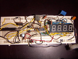
This is the test assembly I wired on a prototype board. The seconds LED is at the far right top corner. The assembly language routine can be downloaded here.