Project: Header
Earlier this summer I decided I wanted a header for my 3L Shadow. Of course nobody really makes one, but I like working with metal so I figured it'd be fun to make one. This is a photo journal of some of the work I did. By no means is this the best or only way to get a header, simply the way I chose.
I did some pricing on raw materials. For just mild steel parts, I was looking at about $200US before shipping and taxes etc. Because I live in the wonderful country of Canada and most of the parts sources I had found were in the US, I also have to factor in brokerage fees for items crossing the border. Add on top of that new flanges, welding supplies, etc. and the price was $350US and over.
So I started looking around for a standard header from another application that I could modify to fit mine. After quite a few hours web surfing, checking out online stores etc. I settled on a header sourced from a 3.8 Pontiac Grand Prix GTP application. It had to be a V6 of course, transversely mounted with the midpipe crossing the transmission on the drivers side and somewhat similar port spacing.
I found an EBay retailer called SS Autochrome who was selling a stainless header for $250US. They seemed to have a large supply because there was one header listed to end each day. They didn't always sell for the minimum $250, but with some patience I finally got one at that price in about 3 tries. I understand they are no longer on EBay, but they have a separate web site. I won't link to it because they are reputed to be an extremely shady dealer. Google them and decide for yourself. There are certainly concerns about the quality of their product. See some of the pics below.
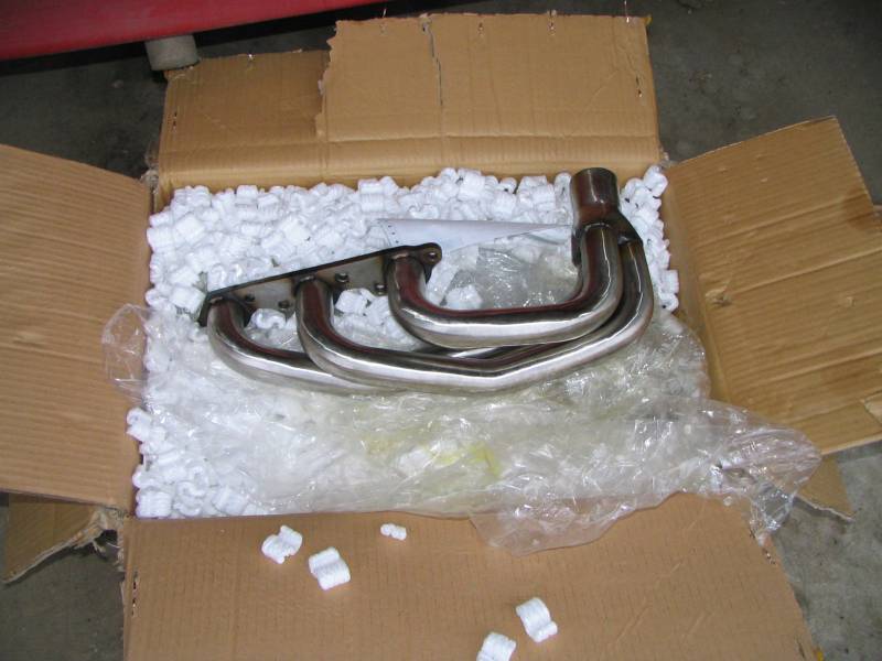
So after my winning bid, my header showed up on time and well packaged.
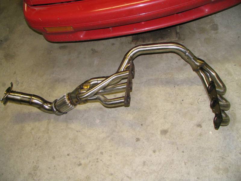
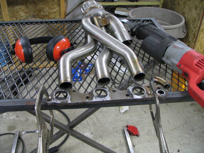
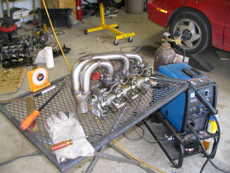
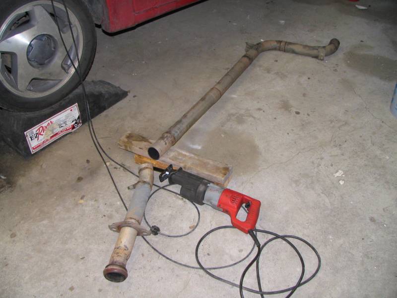
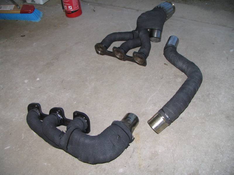
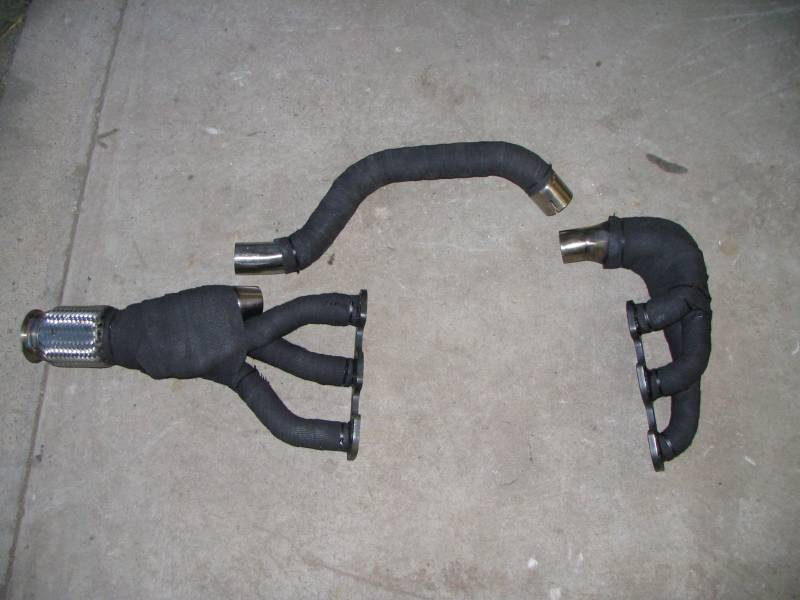
This is the full, unmodified system. The joints appear to be both MIG and TIG welded. The TIG welds look OK, the MIG welds were pretty blobby, but I've seen (and done) worse. The system includes a 3" flex joint where our cat would normally be, two O2 bungs and a 3" to 2.5" transition with a hanger and 2.5" flange.
The bends are not manderel as the ad claimed. Inside the pipes was a weird mixture of sand and what smelled like used oil. I suspect what they did was pack the tubes with a slippery mixture of oil and sand to keep them from collapsing, and bend them on a standard bender. I've heard of sand bending, but the oil is a clever trick although probably illegal everywhere except third world countries. They don't look too bad actually.
The primaries are not 1.75" as the ad claimed, they are actually 1 5/8", which is perfect for my application. The 6G72 flanges I bought have 1.75" ports, but I can neck the primaries up to match before welding. See pics below. The midpipe is 2 1/4". There is no flex bellows on it, but I suspect that's not really necessary. Time will prove me right or wrong.
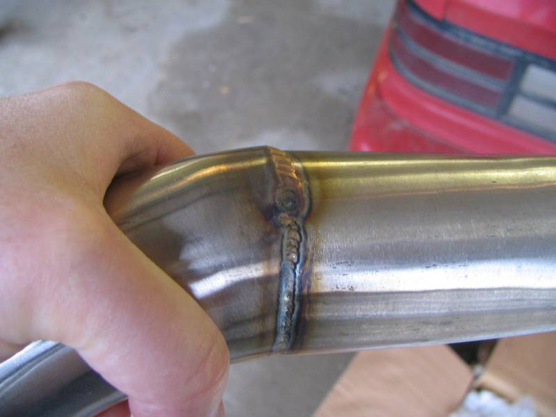
Here's one of the TIG welds. It's not bad, little bit of cratering near the termination and it's blobby in places. This is what you get with a cheap EBay header. The MIG welds actually had a couple of pinhole leaks in places, but I just touched them with my MIG to close them up.
This shows how close the port spacing is between the 6G72 and the 3.8. It's about 1/8" off. I just "adjusted" the tubes with a precision adjustment tool (large hammer) to line them up with the 6G72 flange.
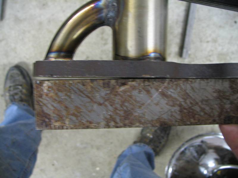
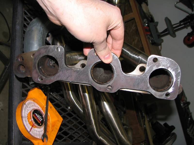
Here's why I wouldn't buy these headers to actually put right on a car: the flange is warped all to hell. This is a pic of a straight edge against the flange. Whoever welded the EGR tube put too much heat into it, and of course it warped. It's possible you could get this to straighten out, but it's definitely not a bolt on.
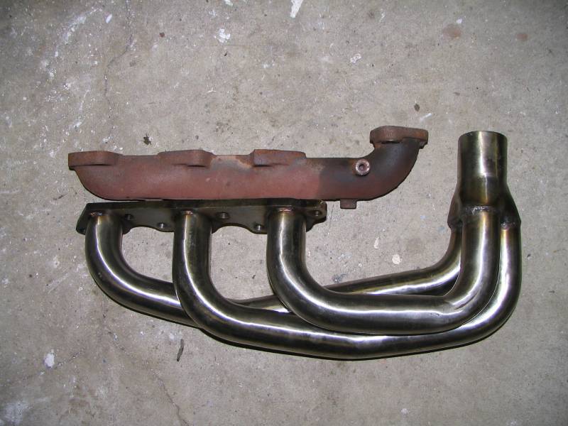
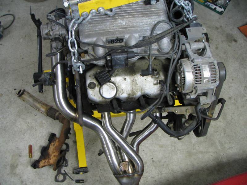
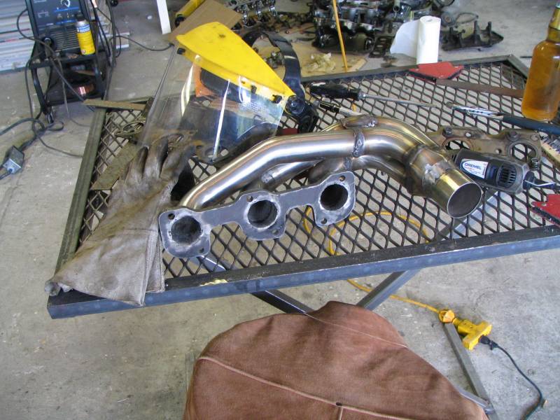
Here's a comparison of the 3.8 front header compared to the stock log manifold. Which do you think flows better?
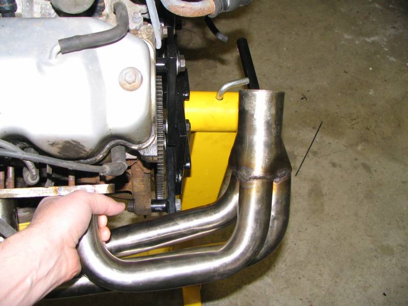
This is one of the "dimensional challenges" of the 3.8 header. It comes way out off the side of the head and runs into all kinds of things. No problem, we'll fix that.
So, time to start cutting up our brand new $250US EBay header. Take a deep breath, remember: "measure twice, cut once". With headers, it's more like measure 20 times, cut once, weld it back on, cut it again. LOL.

Well, here goes nothing! Cutting the back header off the flange, flush. The stainless is pretty tough stuff, I went through several blades.
Few, finally through it.
Cutting off the front header. I planned to take 1" off all three front tubes, but this was actually a mistake. If I was going to do this again, I would cut this one off flush with the flange too, and shorten the tubes individually. See the pics below for the reason why.
I ground the remains of the EGR tube off of the side of the tube. Later on I welded a patch made of some leftover scrap SS tube to close it off. If you were more patient than I am, you could cut a small plug and buttweld it in for a "perfect" fit.
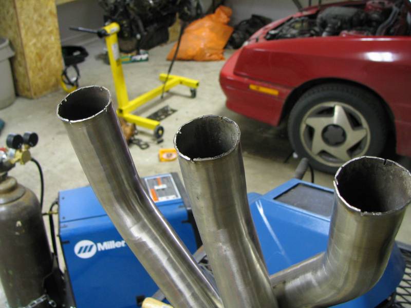
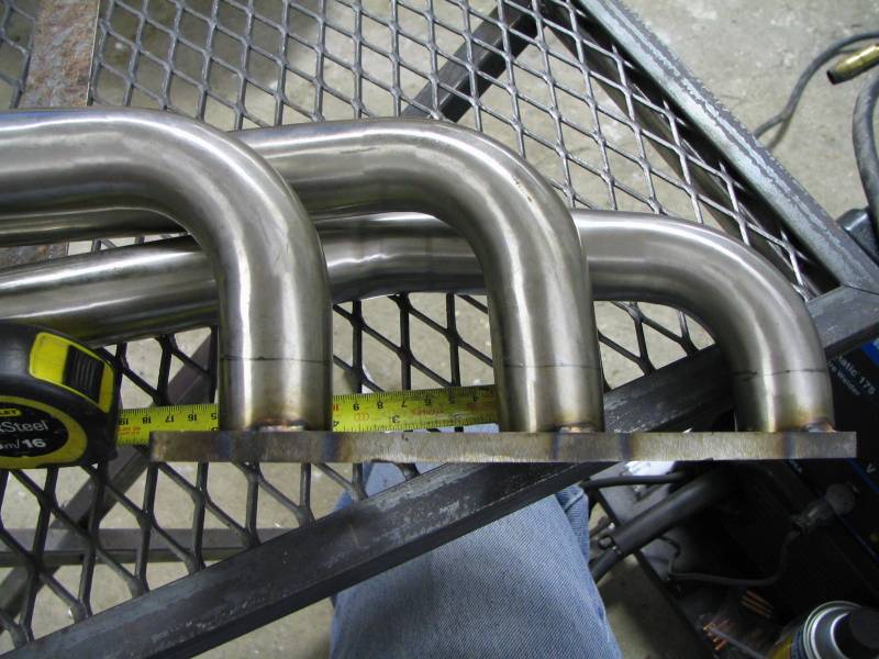
Once the flanges were cut off, I cut four notches in the ends of the tubes and flared them out with a pair of linesman's pliers. I test fit the flange before and after every bend to make sure I was getting them right. It's a lot easier to flare the tubes while they're still all together than after you cut them apart.
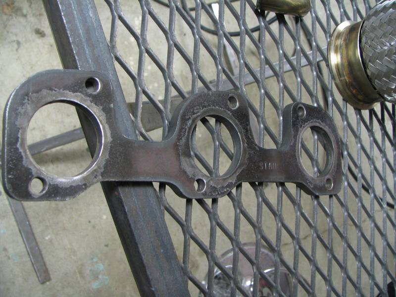
I prepped the flange for final welding now, because once you have the tubes in there and tacked on you won't be able to sand to clean metal very easily. Yes, these are Stahl flanges. Don't buy these. Get them from here instead. They're thicker (1/2") and cheaper. The exhaust studs are not fully threaded, and the thicker flange means you won't have to use multiple washers to space the nut out like I did.
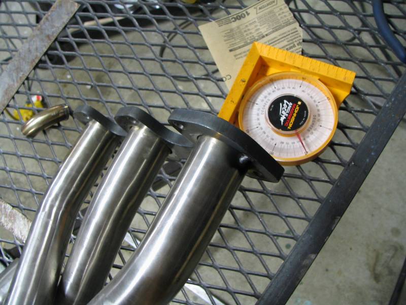
Here I've tacked the rear tubes on the two outside edges only. This will allow you enough flexibility to set the downward angle on the rear header. This is important because it needs to clear both the firewall/tunnel and the k-frame. Don't weld it up any more solid than this yet.
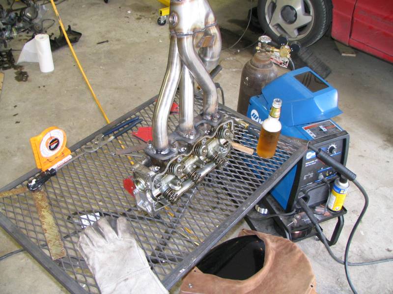
So here we have the rear header bolted up to a mule motor on an engine stand, with the midpipe slipped into the header. The midpipe I actually used without any modifications at all. The downward angle on the rear header was I think about 40 degrees.
Here's a top view.
Here's the top/rear view. This portion of the header was actually almost a perfect fit. I couldn't have asked for much more.
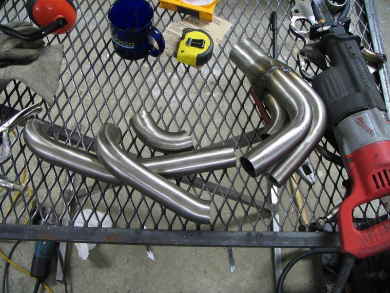
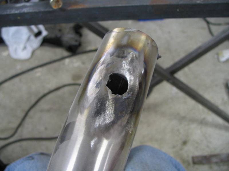
So here's the front header. I agonized over these cuts for literally hours. Why? because you need to weld them back together eventually of course. You need to visualize the welds, place the tip of your welder into the positions that will be required in order to join them back up. I still didn't get it quite right. I ended up cutting a hole in one of the tubes and finishing a weld seam from inside. Not ideal, but it worked. I just welded a patch over the hole when I was done. I took about 3" out of each tube to solve that dimensional challenge I mentioned earlier. Because there are different angles and bends involved, this is probably the trickiest part to get right.
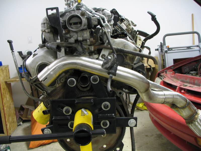
So I finished mocking up the header on the mule motor, tacked everything up temporarily and now it was time for the first actual test fit on the car. After taking this picture I discovered a couple of problems. One was that the midpipe was laying down on top of a shifter cable, too close for my comfort. The other problem was that the coolant pipe that connects the radiator and heater to the crossover pipe was right in the way.
To correct the first problem, I cut a slot in the neck of the front header's collector, adjusted the angle of the tube until it was pointing straight back towards the car, and this allowed the midpipe to "stand up" straighter, away from the shifter cable. I welded the slot back up and ground it out flat.
This shot shows how the rear header tucks neatly into the tunnel. It's close to the floor in one spot but there's a heatshield there and I planned to wrap the header anyway.
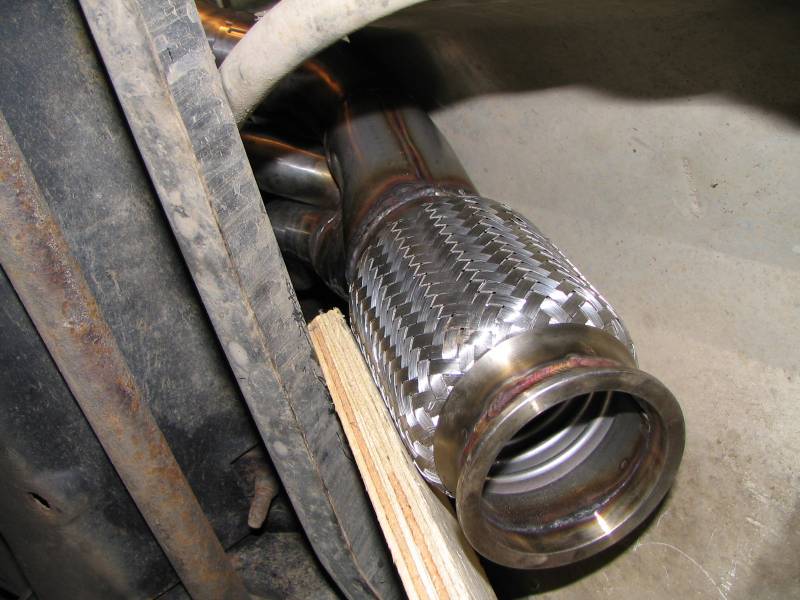
This shows the other end of the header, and where the flex bellows ends up. I put a piece of 3/4" of plywood under the bellows as a spacer to hold it there while I tacked the tubes to the flange a few more times to fix the angle firmly. There's tons of room for this header, but I recommend getting a solid bobble strut to eliminate engine rocking, or you might find that this header will bang around.
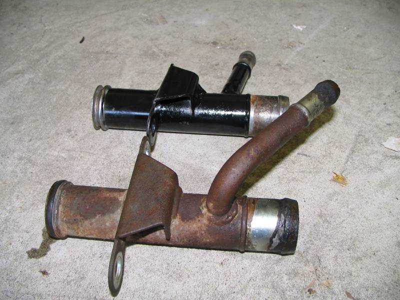
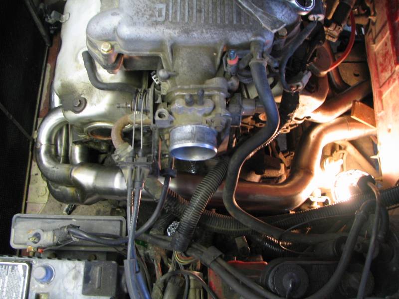
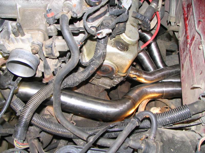
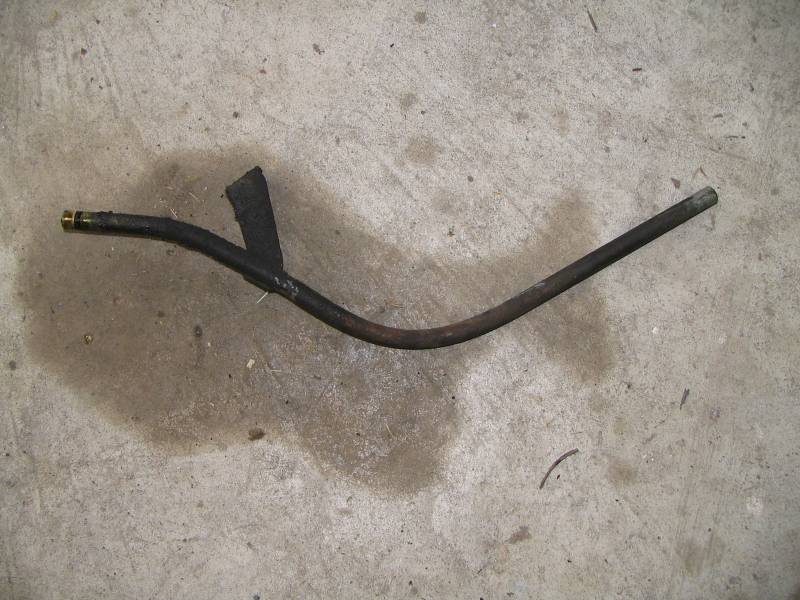
This is how I solved the coolant tube problem. I carefully ground out the welds on the mounting flange until I could pry it free of the tube. The tube for the heater hose I cut off and left about 1/2". I cut the curve out, welded it back on so the whole tube was straight. The mounting flange I rotated 90 degrees and rewelded on to the tube. I cleaned the whole thing and painted it up. You can see the difference between the stock piece and my modified one here.
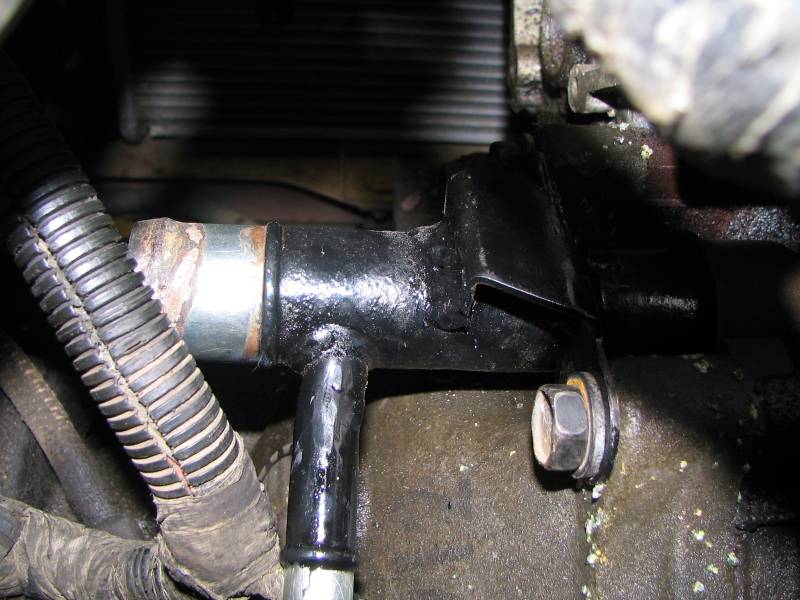
This is a pic of the reinstalled coolant tube, looking from the firewall forward.
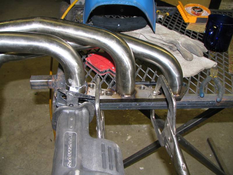
So here's the front header. I welded the tubes to the flange on the inside by welding them in a series of small tack welds. Putting too much heat into the flange at this point would warp it, so I would tack each of the three tubes, turn it over, tack the three again then let it cool for a minute or two. This takes a LONG time to get done, and you have to have patience here. When I was done, I "ported" the entrance to the runners out with a carbide bit and a dremel so that they were a perfect transition from the head's 1.75" to the tube's 1 5/8". I used the exhaust gasket as a guide. I carefully sanded the weld that stood proud of the flange with a flap wheel, being careful not to sand into the flange.
Here's the front header being final welded to the flange. I bolted the header to a head to keep the flange from warping as I poured the heat into the metal. The friggen bolt holes on the bottom of the flange are really close. Once I had finished the welding, I had to port a half-moon shape out of the weld bead to be able to get a nut and washer around the stud.
Here's the front header getting welded to the flange. No welding should be done without a cold beer of course. My American friends won't know what a Sleeman's is, more's the pity. ;-)
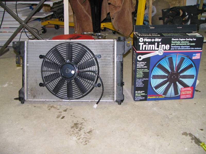
So, one other thing I had to do was create enough room in the front for the front header. Initially I thought if I shortened the front tubes enough, I could keep the stock fan in place, and it was close, but I was about 1/4" too short to be able to do that. So I went to plan B. I bought a Flexalite reversible fan (#114), set it up as a pusher and wired a stock fan plug on it.
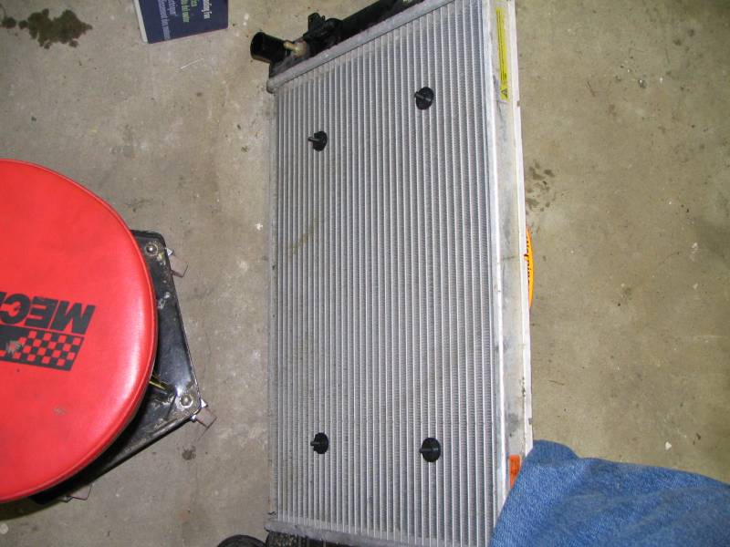
It just pins through the rad with plastic pins and nuts. Easy to do, looks clean. The rad is an aluminum rad I pulled out of another car I had sitting around. The new fan and aluminum rad is 4 lbs lighter than the other brass rad and stock fan, for those counting such things.
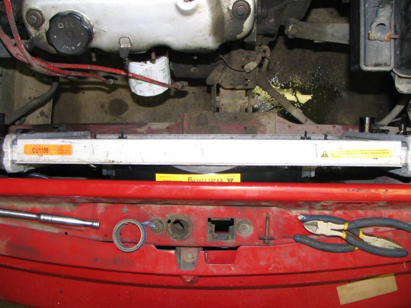
LOTS of room now.
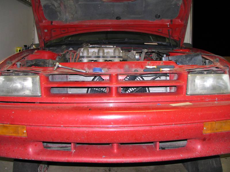
Looks interesting from the front too. ;-) I tested the car with the new rad and fan combo on a really hot day, and everything works perfect. Fan comes on at the 2/3 mark and cools things down in about 30 seconds to the 1/3 mark, which is exactly what it used to do. When moving, the temperature needle never leaves the 1/3 mark.
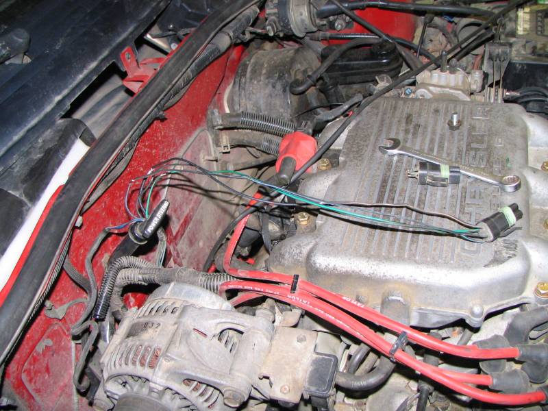
Something else I had to do was extend the O2 sensor wires about 18". I spliced in some wire, soldered them on and covered it with plastic sheath. The first O2 bung is just above the k-frame, and it's relatively easy to install the sensor from underneath the car. I used the second O2 bung that was farther back for my wideband sensor.
I measured and cut the stock midpipe and welded on a two bolt 2.5" flange, which mates up with the flange that came from the kit. I could go 3" but frankly it's a pain to get over the rear axle and I think 2.5" is plenty for a normally aspirated 3 liter. I was careful to keep all transitions smooth and flanges lined up properly.
I also had to modify the dipstick to clear the header. I think this is the "before" shot, I don't think I took an "after". Basically I just hammered the bends out of the tube and cut about 1" out of the mounting flange and welded it back together. Having the mule motor on the stand to do this on made it a piece of cake. I ended up putting a bit of bend back in, but the tube is so soft you can easily bend it by hand while it's on the car.
Something else I did but have no pictures of is I moved the oil pressure sensor. I got a double-male NPT and a 90 degree double-female brass adapter and screwed it into the stock hole, threading the sensor back into the female 90. I used RTV as a thread sealant. The end position has the sensor pointing forwards and down instead of sideways across the front of the motor. The stock position parallels one of the header tubes and places the plastic sensor within 1/4" of the tube at one point, which was a little close for me.
Finally, I wrapped the header in DEI 2" header wrap. Something else you should consider when designing the header is to make sure you leave at least 1/4" between the tubes if you plan to wrap them. I had to improvise in a few places, but I managed to get them fully wrapped up to my satisfaction.
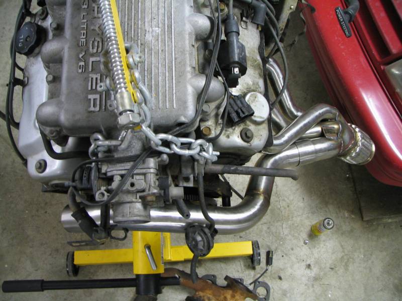
This is the final product. One final thing to consider when laying out the header is access to the nuts. I didn't pay enough attention to this area, but I got really lucky. Some nutss I can only reach with a wrench, and one nut I can only tighen with a U-joint on a ratchet, LOL. I suggest fully installing your tacked-together headers, attaching all nuts before you do your final welding.
So, the final question is: what do they do? Well I can't put any numbers on them yet, a buddy and I are going to dyno our cars this week. Unfortunately I did a couple of other mods around the same time so it won't be a conclusive difference from my last dyno session. I did take the car out for a test drive when the only change I made was the headers and I can say that the engine feels a lot less "strangled" with the headers vs the stock log. The power comes on smooth, and there is a noticeable bias towards the top end. You get on the throttle and the car sort of "whooshes" forward and before you know it you're way over the speed limit.
I suspect that part of the problem is not so much that the power has shifted upwards (although that might be true) but that the lower RPMs are somewhat lean. As I mentioned above, I do have a wideband rig and a datalogger. I logged several runs, and the A/F is a touch lean from about 2500-4000 rpm which I suspect is hurting power in that area. I have a plan to address that.
Some notes:
- The flange is mild steel, and the tubes are stainless. The correct wire to use when joining these metals is ER309, I used ER309L just a higher grade (it's what they had at the welding supply shop). The gas to use for stainless is argon.
- I used about a roll and a quarter of the header wrap. You could probably get away with just one roll if you didn't wrap as much of the rear header as I did. I wanted to keep it from heating up the floor as much as possible. I also sprayed the wrap with silicone paint, which repels water.
- Because the headers are wrapped, when you park the car heat tends to feed back into the motor through the flange over time. The intake when you park it will be cool to the touch, and a few minutes later will burn your hand. I recommend using synthetic oil if possible to prevent coking, much the same reason it is recommended for turbo cars.
- When not using the wideband in the second O2 bung, I just plug it with an old O2 with the wires cut off.
- The flanges were flat when I got them, and flat after I finished my welding. I told myself that I would have them surfaced at a machine shop if they leaked when I had installed them, but so far no problem.
- I used 2 1/4" T-bar clamps on the two midpipe joints. The tubes are punched for a squeezeable slip joint, but you need to cut them open with a Dremel so the lips of the pipe "squish".
- I had to redrill some of the holes in the flanges, they weren't quite the right size.
Stuff I would do differently:
- I was hasty and cut some of the tubes too short (particularly the front header tubes) before I really knew what I needed. As a result, some of the bends on the front header could be a bit more gradual but honestly it's not that big a deal. Trying to get equal length in that tight a space is not worth driving yourself nuts.
- If I won the lottery, I would have rather done the welding with a TIG, but my MIG welds were more than adequate.
- I would have bought the cheaper 1/2" flange. I didn't know they were for sale until after I'd bought the Stahl ones.
So far I have about 2000km on the headers and they are working great. Before the headers I had a 2.5" manderel exhaust, no cat and a Flowmaster 50. It really isn't much louder now than it was then (but mind you, it's always been fairly loud). The sound has changed for the better in my opinion, it has that cool warbing V6 sound to it when I stand on the loud pedal.