The
Trials of Hydrophone #1
The
Preamplifier ... design considerations
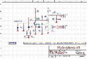
First of all the electronics. The 'phone itself is a
preamplifier consisting of an MPF103 JFET direct coupled to a BC558 pnp
transistor. The output is a balanced wire pair using the CT of an AF transformer
as GND reference. Two back to back 1N914 diodes provide input limiting.
There's provision for remote gain control via a 5-pin output socket. The
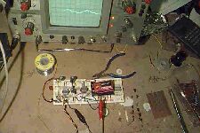
device was breadboarded and tested on PROTOBOARD before a PCB was constructed.
The whole contraption was then fitted inside a small plastic 'jiffy' box.
Gain, on the breadboard, seemed to be about 10 dB.
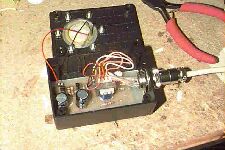
The acoustic element was piezo crystal from an audio
'buzzer'. It was bonded with Araldyte resin, very thinly applied, to an
hexagonal piece of 0.5 mm aluminum. The aluminum plate was bolted to a
hole in the jiffy box' lid via six 3 mm drill holes on its perimeter. All
seals were water proofed with silicone sealant and/or modeling glue. The
cable connector was sealed with self amalgamating tape. Negative buoyancy
was achieved by araldyting lead sinkers along the inside walls of the box.
NEXT time, I'll use polycarbonate plastic for the sensing
element, instead of aluminum. Gaskets are essential too. The gizmo kept
working for two weeks in a bucket of water but glued seals are too fragile
for use in the sea. A modest impact causes the sides of the box to flex
and in comes the water. Saltwater is instantly FATAL to electronic circuitry!
The
Buffer
Amplifier & Recorder
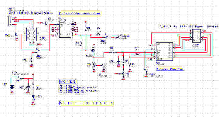
The buffer amp consists mainly of an LM380 power amp
to boos the signal to driver levels. It has a dual gang pot at the input
to allow balanced input from the preamp. This is, if necessary, to reduce
common mode noise picked up in the water. There's an attenuating
common emitter amp at the LM380's output to allow recording whilst simultaneously
listening. There's also an LM3914 LED level indicator so one can monitor
signal levels while listening and/or recording. Total BW is about 20 kHz
but I haven't accurately measured it yet. The whole thing, including the
9V battery harness, was built on a PCB and fitted inside a plastic jiffy
box. Both schematic and PCB design were done using WinDRAFT and WinBOARD
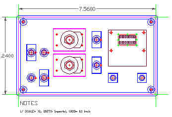
from IVEX. The layout of the control panel was accurately designed using
IntelliCAD.
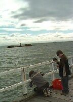
OK, the pier at Black Rock
ain't exactly the Kaikoura Canyon. But it's a start ...
We got about 10 minutes worth of recording, then the hydrophone
case sprung a leak. Mainly 'cause friend "Cone-head" sitting my right,
just had to keep clonking the gizmo up and down on the bottom.
Obviously a hydrophone casing has to be physically tough. Not just to withstand
water pressure but also to hold up against impacts. Also, the sound level
was pretty low, even when boosted by the buffer amplifier. Seems to me
you need about 40 dB of gain at the front end. All design points for version
#2, I guess.
So what sounds did we hear before the hydrophone case
gave up? It's a weird audio environment down there : I had no idea at all
what to expect. It sounds sorta like rain on a tin roof. You could
hear waves sloshing, probably against the pier, bubbles, the very faint
sound of waves breaking on shore and lots of unidentifiable crackles and
snaps. Towards the end of the file a boat fires up its engine about 500
m away. You can hear engine noise underwater quite clearly.
Here's a
WAV file (225 K) of part of the recording. I doubt if anyone apart
from me would be interested, though.
Copyright
© 2000 to Ian Hynes. All rights reserved. The Quest for Thylacoleo
: http://www.thylacoleo.com