Ford 429 Engine Rebuild
This 429 Engine is being built for a 1968 Ford Thunderbird. The 429 is part of the 385 Series engine built by Ford, which includes the 460. They both share the same block, with different Crankshafts to change the displacement. This engine was introduced in 1968, and features an 11:1 compression ratio and pushes over 400 HP in stock form. After a few years, Ford had various changes to the engine which increased the Deck height and lowered the Compression, resulting in a loss of power.
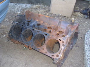
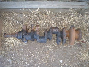
The engine that originally came out of the 1968 Thunderbird was taken to a shop for machine work before the buildup process began. Unfortunately, Kaeding Performance in Campbell, Ca. caught on fire and burned to the ground. This engine was inside of the building at the time and suffered major heat damage from the fire and warped being cooled when the fire department came. These pictures show the burnt remains of the engine block and crankshaft.
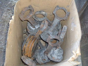
Several of the engine components were with the Engine and Crankshaft as well, including all of the Piston and Rod assemblies, which were still good at that time. Some of the pulleys and other components were also burnt in the fire, resulting in a total loss of the engine.
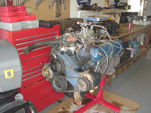
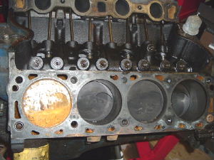
Many months later, another 429 Engine from a 1971 Thunderbird was found, which is identical to the original 1968 Engine. Upon arrival, it was completely disassembled, revealing a large deposit of rust in the #5 cylinder, most likely due to the intake valve being open and water seeping into the Intake manifold after sitting for several years. The engine block was taken to a local engine machine shop where it was bored .030" Over, making sure all other clearances were correct and thoroughly cleaned upon arrival. The Crankshaft was sent to Ed's Crankshafts in San Leandro, Ca. where it was magnafluxed to check for cracks or imperfections and polished down .010". The Crankshaft and all Pistons and Rods were taken to another shop where they were all balanced before engine assembly begins.
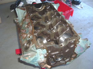
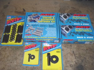
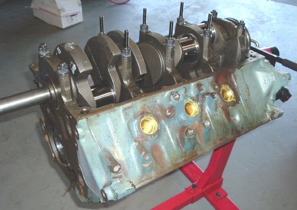
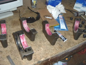
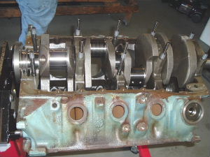
Here is the block on the engine stand after being thoroughly cleaned. The Thread holes were all chased using a tap to clear out any debris and rust. All of the oil passages and cylinder walls have been cleared out in preperation for the rebuild. The engine will be completely assembled using ARP high strenth Bolts and Studs. There are several sets here including Rod Bolts, Crank and Camshaft Bolts, Complete Engine assembly Kit, Head Studs and Main Studs.
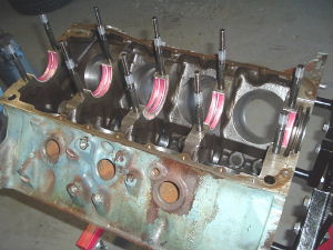
The Main studs have been hand threaded into the Block, and the Main bearing shell halves were placed into the Main bores, with a coat of Redline Engine Assembly lube on each bearing. Clevite 77 Bearings are being used for this engine. The Rear main seal is a Split lip design and is installed offset to ensure a proper seal with no leaks.
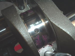
The Crankshaft is then carefully put into place, and a small piece of Plasti-Gage is placed on each Main Journal to check for Main clearance. It is important that all of the Main clearances are within specs and close in size to eachother as this has a direct effect on oil pressure and crankshaft lubrication. The Main caps are then put into place - with no assembly lube on the upper bearing caps as the Plasti-Gage is oil soluable and will start to dissolve in Oil. The caps are then torqued to specs, with the Middle Cap tightened down last. The nuts are first tightened snug, then Torqued with a Torque wrench. Then they are all removed and compared with the Strip gage that comes with the Plasti-Gage to ensure they are within specs. All of the clearances are very close together and within specs, so the main cap bearings are coated with Assembly lube and re-installed.
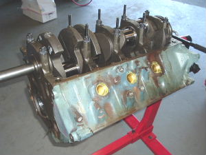
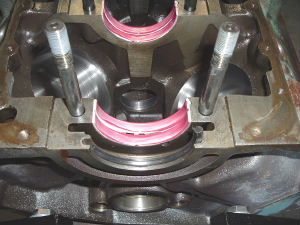
The engine is shown here with all caps in place except for the Middle cap which is being installed last. The middle cap features the Thrust Bearing, and the crankshaft is pulled backwards during the tightening of this cap using a large Flathead screwdriver wedged between the Crank and a Main cap. After all of the Main caps are installed, the Crankshaft endplay is checked. The crankshaft is wiggled back and forth to seat the Thrust bearing. Then, a dial Indicator is placed on one end of the crankshaft while the crankshaft is pryed to the rear most position and the indicator is set to Zero. Next the crank is pryed all the way forward, giving us an endplay of .006" which is within specifications. The Freeze plugs have been installed into the block with Sealant coated around the openings and the plugs pounded into the block.
Assembly still continues as the Rings are being filed down and pistons installed. More pictures to come soon. Last updated 5.17.06
Back to Main