POWER SYSTEM
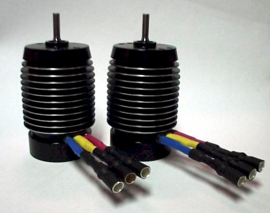
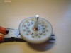
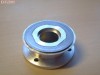
To punch through air at around 100mph, you need a lot of power. Many people have suggested power plants to me, but none can come close to the compact and ultra efficient DC brushless electric motors. The best ones are made by ModelTech, right here in the UK. Brushless motors have the magnet on the rotor and stationary coils around the inside of the can, like an inverted brushed motor. The only things touching the rotor are the 2 superb quality bearings supporting it. With no friction or high electrical resistance from brushes, BL motors can achieve in the region of 30% more efficiency than brushed motors, and are much more powerful at a given size. The acceleration is vastly better due to low rotor inertial moment (no heavy iron to rotate), and so is the top speed. ModelTech BLs can spin at over 100,000RPM. Brushed motors can't even get close to that. The downsides are the high cost, and requirement for special BL controllers, which are also expensive but absolutely essential to the systems' operation. ModelTech have stopped importing BL motors now it seems, but the same products are available through West London Models and I am sure others who sell Hacker motors. Hacker have now developed some very promising looking car specific controllers too, with the help of Jeti.
BALANCING ACT
To go as fast as possible, you need to transfer as much POWER as you can from the battery to the ground/air. As previously mentioned, the brushless motor is the most efficient method to do this in a wheel driven car, with around 90% efficiency. But you can't just leave it at that. ModelTech BL controllers are limited to a constant current draw of 70A, or a peak draw of 100A for 15 seconds. At high current draw, we estimate the average cell voltage to be 1V, in each of the 18 cells in the fully prepped car. This gives us a maximum input power of 18*100=1800 WATTS. The efficiency of the motor/drive system is approximated as 88% at this level, giving a max. power transfer of 0.88x1800=1580 WATTS. This equates to about 2.1 HP, better than you will get from a .21ci nitro engine, but of course at a much higher RPM.
This is the next problem to consider. The car's gear ratio has to be adjusted so that the current draw does not go above 100A (absolute max limit), and the motor RPM does not exceed 100,000. The following results are from calculations using a gear ratio of 30-81 (2.7:1) and a tyre diameter of 65mm:
MAX VEHICLE SPEED AT 100A, 100,000RPM = 126m/s = 282mph
Assuming no friction (resistance) at this speed. Of course this is completely inaccurate because at 100mph drag forces are huge. However it does show, that even using a low gear ratio, we will not have to go near the motor's max RPM limit of 100,000RPM, which is reassuring. (I have already written off one of these motors in an accident, I don't want to do it again!).
To get an accurate model of the possible max speed of the car, you have to know how the drag force on the car changes with speed. At very low speed, the drag is directly proportional to speed, but in our regime it is likely to be of the form F=cV^x, where x is between 2 and 3 and c is a constant value that we would also need to know. c depends on the shape of the car to a great extent, ie using a more aerodynamic body will reduce c and therefore the drag force F. F is pulling the car in a backwards direction, so the smaller, the better! Maximum speed will be attained when F=D, the drive force. |