Tools Used:
Dremel Rotary Tool:
Cut Off Blades
Grinding Stones
Buffer Heads
Rigid Pipe Cutter
Rat Tail File
Flat File
Medium Grit Sand Paper
Ultra Fine Sand Paper
Scotch Brite
|
Details of Construction |
|
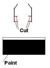
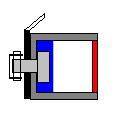
| Step 1:
Start out by cutting out the two peices for the emitter section out of 1-1/4" PVC. The second piece shown is a collar that will slide over the top piece to give us the raised section on the emitter. To accomplish this, cut a slit on the bottom of the second peice. This allows you to bend the pipe outward and slide it over the main emitter section. |
|
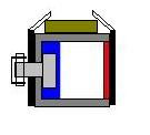
| Step 2:
Mix up some 2 Part Epoxy (I use the 90 second type) and smear it along the inside of the collar piece (second piece shown in Step 1.). Slide the collar piece over the main emitter section as shown in the image to the right. Wipe away excess epoxy. Hold the collar tightly and securely in place while the epoxy dries. After the epoxy has hardened: Sand all edges. Fill voids with Bondo and re-sand. Paint Flat Black. |
|
| Step 3:
Cut a 1-3/4" piece of PVC. Sand the edges until smooth. Paint Flat Black.
|
|
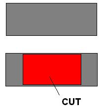
| Step 4:
Cut two 1-3/4 pieces of Macklanburg-Duncan "Universal Door Jamb Weatherstrip" (UPC 4337401040). Cut inner rails from the strip (marked in Red). Mask the angled part of the weather strip. Paint sides of weather strip flat black. |
|
| Step 5:
Cut one 1-3/4" piece of 1/2" square steel tubing. Cut a section out of the side of this piece so that you will be able to place the screw for the toggle bolt onto in side of the square tubing. |
|
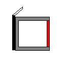
| Step 6:
Use 2 Part Epoxy to glue one piece of the weatherstrip to the square steel tube as shown. Allow to cure well. |
|
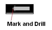
| Step 7:
Take the glued section from Step 6 and Position the toggle bolt head on the Weatherstrip as shown. Mark and drill a hole for the toggle bolt's screw..
|
|
| Step 8:
Attach Toggle Bolt Head with Screw as shown. (Hint: You will have to cut the screw). Tighten the screw tight so that the Toggle Bolt does not move! For good measure... Put 2 Part Epoxy on the Screw Head inside of the square tube.
|
|
| Step 9:
Cut a 1-5/8" piece of PC Card Bus Connector from the PC Card. |
|
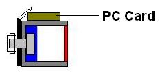
| Step 10:
Epoxy the PC Card piece onto the top of the Square Steel Tube as shown. |
 |
| Step 11:
Epoxy the other piece of weatherstrip to the assembly as shown. This step completes the switch assembly! |
|
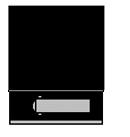
| Step 12:
Epoxy the completed switch assembly to the 1-3/4" piece of PVC mentioned in Step #3 as shown. Use Bondo on the seam areas between the PVC and the switch assembly to create a nice curved fit. Fill the ends of the switch assembly with Bondo. Sculpt edges with a utility knife. Allow to Cure. Sand until all edges are smooth. Mask and Re-Paint flat black.
|
|
| Step 13:
Cut six 1/2" grip pieces out of PVC. Each grip piece will be 4" long. Drip end holes 1/4" from each end on center.
|
|
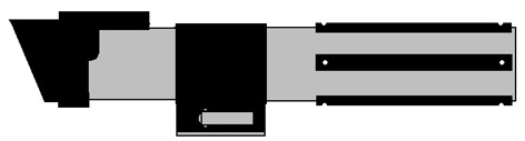
| Step 14:
Epoxy the Emitter Section onto the 1-1/2" Sink Tail Piece. Attach the Control Switch Band in place with a Rivet. Attach the Grips onto the 1-1/2" Sink Tail Piece with Rivets. I have a template you can use to drill the holes... Will post it soon. Paint all rivets black. The end result will look like the below.... :) |
|
|
|
|