I bought my LCD from Electronic Inventory Online (EIO) store, which website is located at www.eio.com. They sell quite a variety of LCD for an affordable price too. I bought myself 3 units of Seiko L1642B1L. They are the older variant of the newer 1682 16x2 LCD units. The only drawback about this LCD is that this LCD unit seems to have low level of contrast. Even at maximum contrast, you can barely see the text on the LCD screen. To correct for this problem, I used the LCD's backlit to get a better view of the text on the LCD.
The datasheet for all Seiko Instruments LCD can be found here, at Seiko Instrument's website.
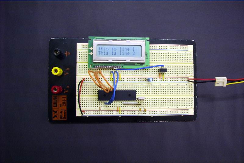
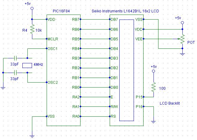
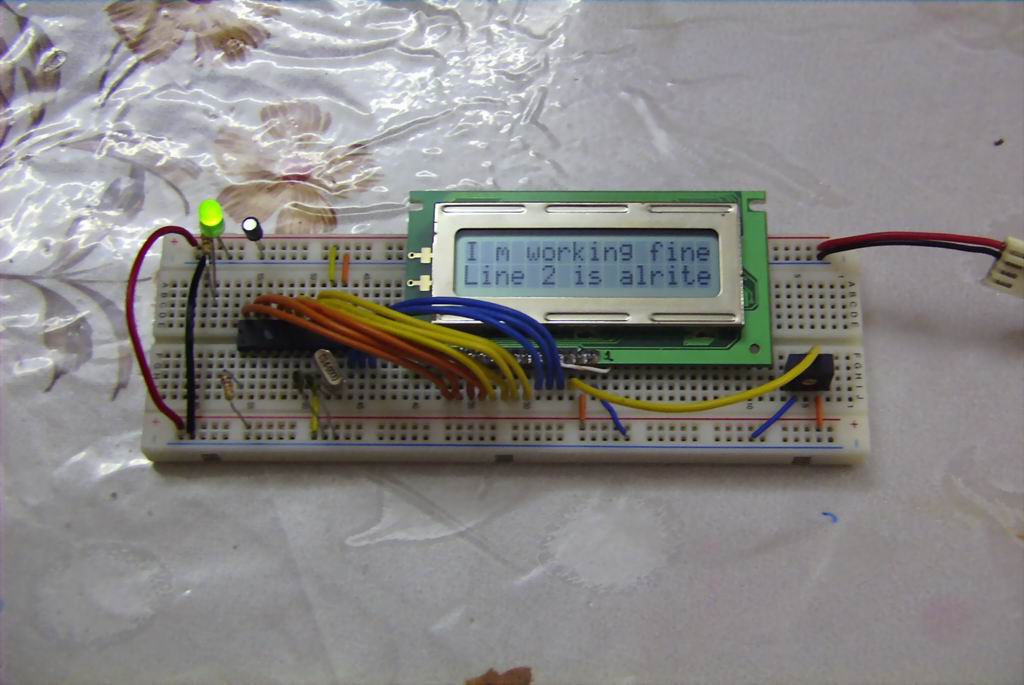
Presented here are the source code and the schematics for this project. The code is written according to the instructions shown in the datasheet. The source code is quite clearly documented and remarked so there isn't really a need to explain about its operation over here. Also included are some pictures I took on the circuit.
Source code : seikolcd.asm

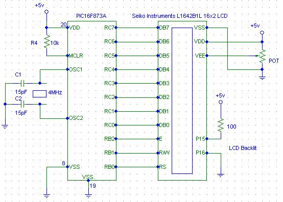
Then, I decided to write a more optimized code than the above by reducing the size and the execution time of the programme by using shorter delay time. This way the the instructions executed faster and at the same time, has sufficient delay to complete its execution. Presented below are the new schematics and source code. This code is written for PIC16F873A instead of PIC16F84. Just change the connections from PORTB to PORTC for the LCD datalines DB0 to DB7 and the RS, R/W and E lines from PORTA to PORTB. It can be used for any other 28 or 40 pins PICMicro such as the PIC16F873, 876, 876A, 877, 877A and etc. by changing the **include 'p16f84.inc' to p16f873a.inc and the connections pinout.
Presented below are the source code and the schematics for the PIC16F873A interfacing.
These simple programmes can be used as a display test of the LCD before actually starting on a project that requires the use of the LCD. This way you can be certain that the LCD actually works before implementation. I will improve on these source codes and implement them in future PICMicro Pet Projects. :)
Source code : seikolcd873a.asm
A more optimized and faster code ==> seikolcd873_2.asm
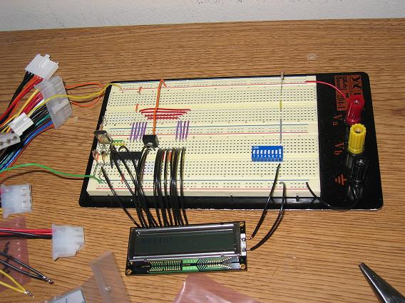
For the seikolcd873_2.asm code, the pinout is slightly different. The data pins (DB0-DB7) now goes to PORTB of the LCD while RS, R/W and E pins now goes to Pin RC0, RC1, and RC2 respectively. I also included a picture of the circuit built using the above code below.
Source code : asd.zip