| The Dark Eldar Despoiler conversion
vehicle
- A new transport based upon the Dark Eldar Raider chassis |
 |
| By Dan Moore |
e-mail |
Return to
my
Dark Elar Home Page |
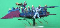
I have received several requests for information on how to make the Despoiler transport that is featured on my Dark Eldar website. In response to this I have decided to present detailed information on the whole conversion process. The original concept for the vehicle arose when I decided to modify the Raider transport so that it could hold a full complement of 10 models. Over time the concept evolved into a custom transport for a new Dark Eldar troops choice that I created called a Slaver Squad.
The Despoiler transport involves several modifications to the Raider. The Driver is moved forward into the nose section of the vehicle. The gunner is mounted on a pedestal behind the driver. The decking for passengers is extended both fore and aft on the vehicle. The tail section is modified to have a lower profile. Trophy racks are added around the decking to form a railing to hold passenger models in place. Slave snares are added. The Dark Lance is converted to a Horrorfex.
Raider model – assembled or disassembled
Sharp razor knife (Xacto or similar), Razor saw or jewelers saw, Jewelers Files
Rotary tool (Dremel) with abrasive cutting wheel,
Polystyrene glue, 5-minute epoxy, plastic putty
1/4-inch (6.4 mm) polystyrene tube with 4+ inch length (I use tube from Evergreen Plastics)
5/16-inch (7.9 mm) polystyrene tube with 3+ inch length, it must slide over 1/4-inch tube (I use tube from Evergreen Plastics)
0.062-inch (1.6 mm) polystyrene sheet (2 inch x 1 inch piece),
0.030-inch (0.8 mm) polystyrene sheet
0.188-inch (4.8 mm) x 0.100-inch (2.5 mm) polystyrene strips
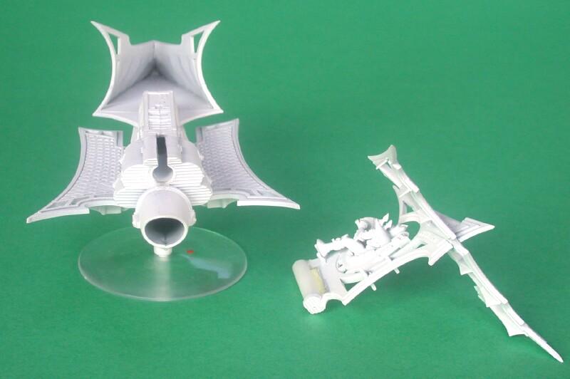
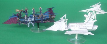 The white Raider model in the
foreground will be converted
into the Despoiler model in the background |
This procedure has been explained in detail on a separate page on my Dark Eldar website. You can find it by following this link.
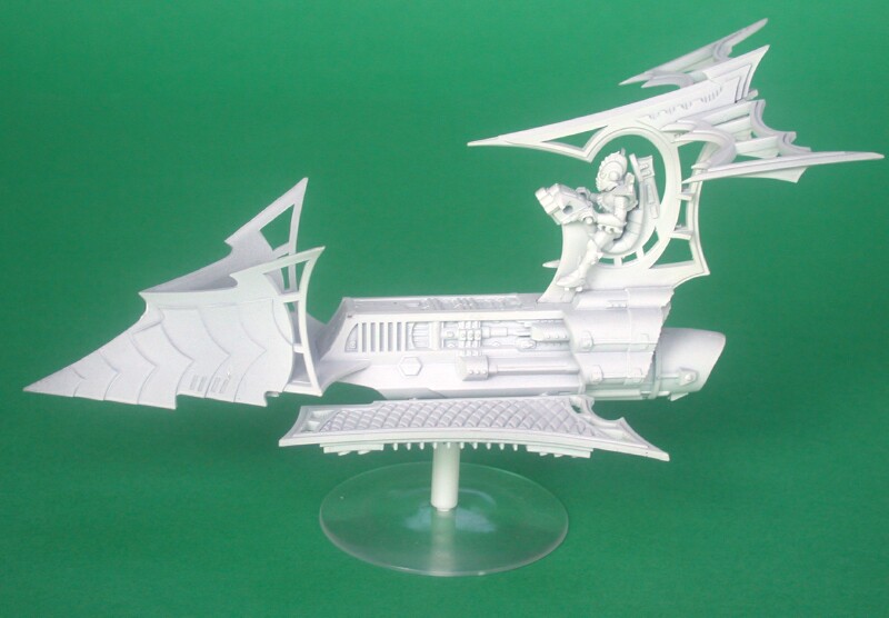 The assembled Raider model |
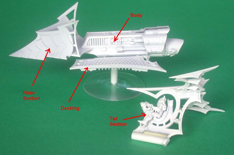 The Raider with the tail section removed |
 A rear view of the raider showing the slot for the tail |
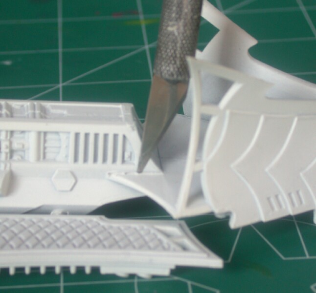
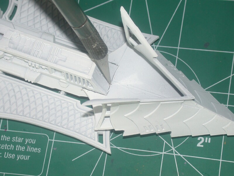
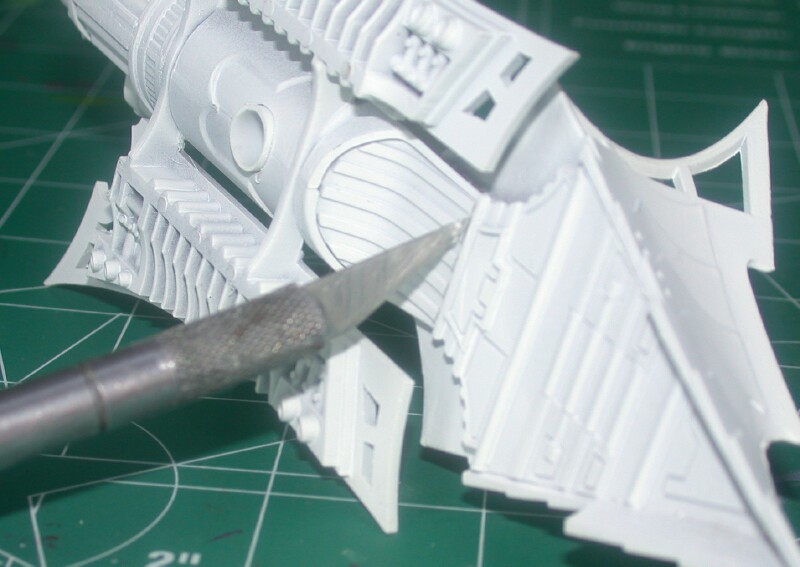
The nose section of the Raider will need to be cut away from the main body so that the body and decking can be extended. The nose section is roughly triangular in shape and is normally where the dark lance and gunner would be mounted. The nose section can be removed by using a sharp hobby knife to first score and then cut through the model around the rectangular end of the Raider body. The bottom side of the Raider will also need to be cut where the air intake scoop is located.
|
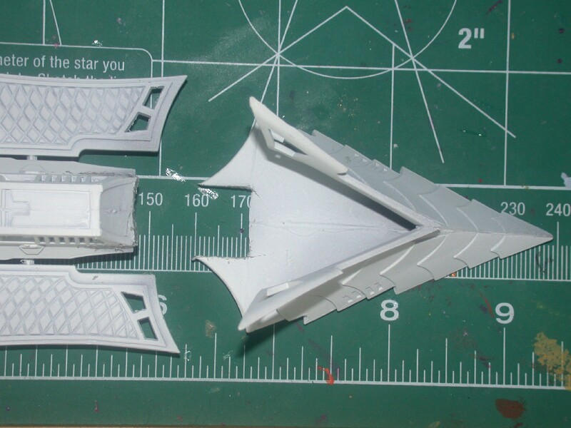
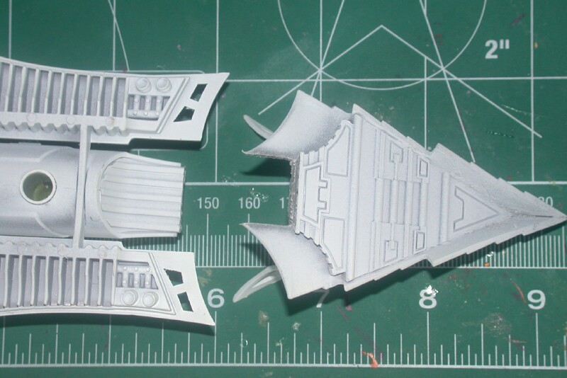
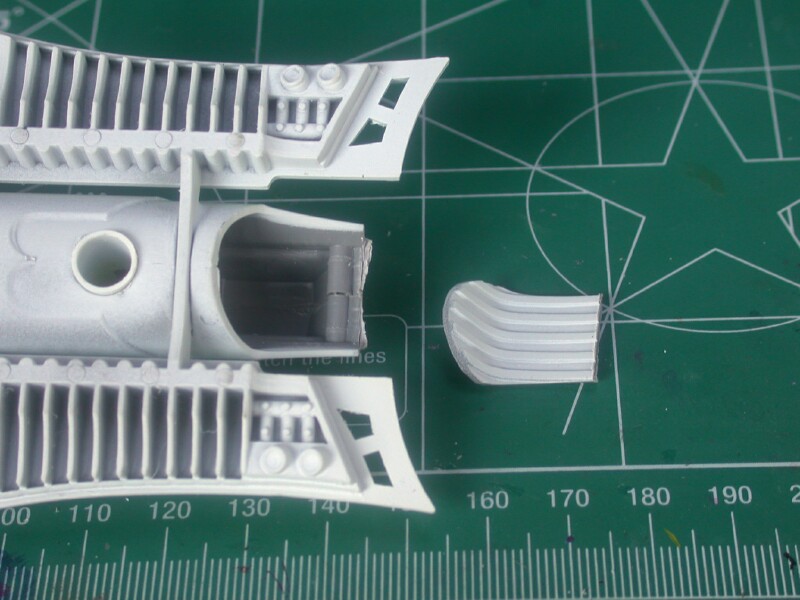
In order to extend the length of the Raider two layers of polystyrene sheet will be cut and glued together to reconnect the nose section of the Raider to the main body. The first piece of polystyrene will be cut from 0.030-inch sheet. It will be custom fitted to match the existing decking/front section and overlap them slightly on the bottom surfaces so that they can be securely glued.
A piece of polystyrene sheet is positioned between the top surface of the Raider decking and the air intake scoop. An ink pen is used to mark the perimeter of the decking. A small offset (approx. 0.125-inches) is allowed around the perimeter so that the sheet will overlap with the decking. Once the sheet is marked, the nose section of the raider is placed on top of the polystyrene sheet and and positioned to extend the triangular shape approximately 1 inch. A metal ruler or straight edge can be used to mark the shape of the sheet. The 0.030-thick sheet is then cut to size with a hobby knife. The piece will require further trimming to fit the front secton of the Raider.
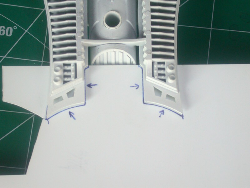 The 0.030-inch polystyrene sheet is inserted between the decking and air scoop and marked. The arrows indicate the direction of the overlap with the decking. |
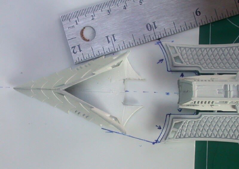 A metal ruler is used to align the nose section with the deck to extend the triangular shape. The other half of the triangle is already marked with a pen |
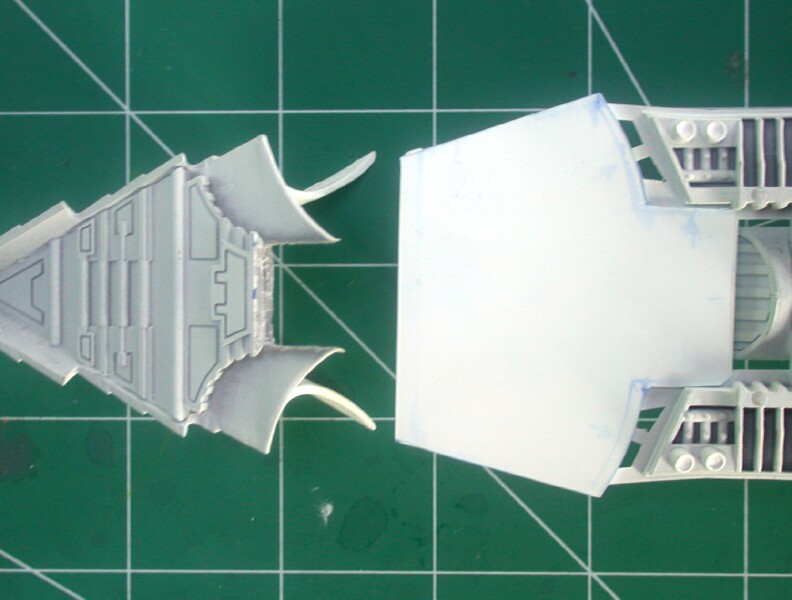 A view showing 0.030-inch polystyrene sheet cut to size. The piece requires further trimming to fit the nose secton of the Raider. |
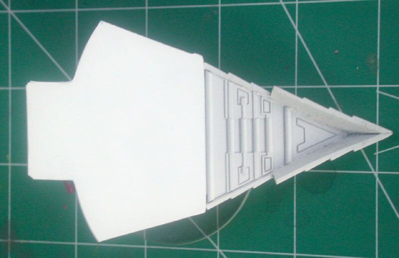 The 0.030-inch polystyrene sheet is aligned with the nose section of the Raider |
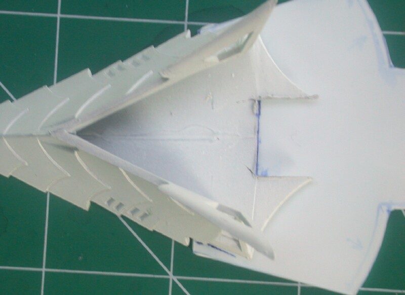 The perimeter where the nose section was cut away from the Raider body is marked with an ink pen |
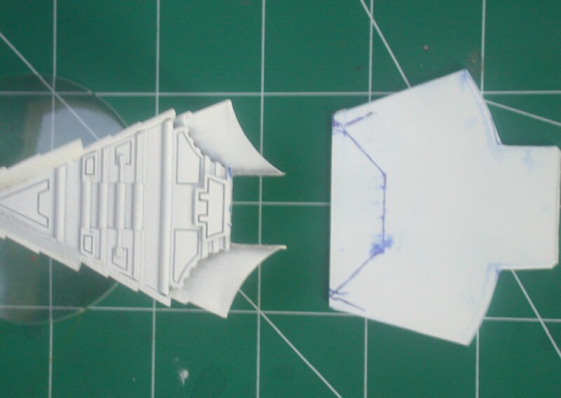 A view showing the polystyrene after it is marked . Note the trapezoidal shape of the area to be removed. |
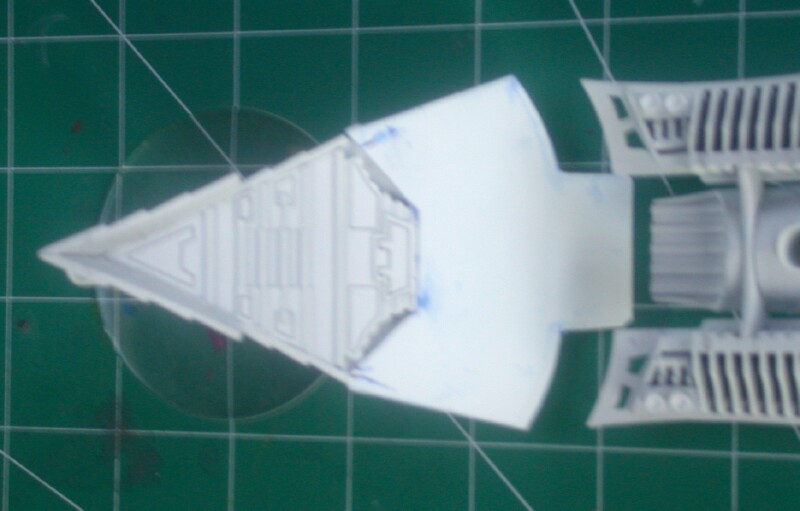 A bottom view of the nose section showing the overlap fit with the cut polystyrene sheet |
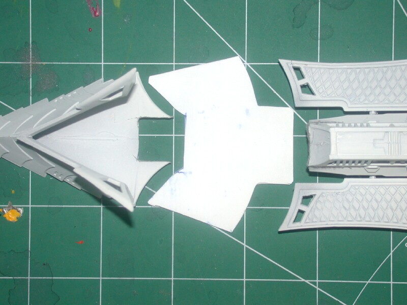 A top view showing the Raider nose section and body with the newly made polystyrene deck extension between them |
The 0.030-inch polystyrene sheet was cut to make a piece to extend and join the Raider nose with the Raider body and decking. There is an overlap between the sheet and bottom of the Raider components so that they can be glued together. An additional piece of 0.062-inch polystyrene sheet will need to be cut as a filler piece to create a smooth transition from the top of the Raider decking to the floor of the Raider nose section where the driver will sit.
The simplest method to determine the size and shape of the deck filler piece is to mark its outline on the deck extension piece that was made in Step 3. The deck extension is first positioned against the bottom surface off the Raider nose section. The perimeter of the nose section is then marked on the top of the deck extension.
Next the deck extension is positioned against the bottom surface of the Raider body with the appropriate amount of overlap. The perimeter of the decking and raider body is then marked on the top of the deck extension.
The area marked on the deck extension should define the size and shape of filler piece that is required. Tracing paper can be used to create a template for the deck filler piece.by copying the perimeters that were marked on the deck extension piece. The deck filler piece should be made with 0.062-thick polystyrene sheet so that it matches the thickness of the decking.
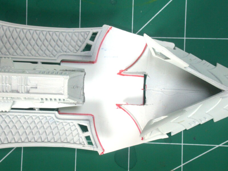 The deck extension is aligned with the nose and deck of the Raider and the perimeter of both is marked with an ink pen. |
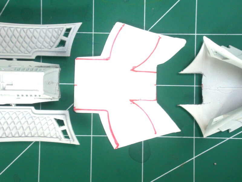 A view showing the perimeter of the the deck and nose sections marked on the deck extension. |
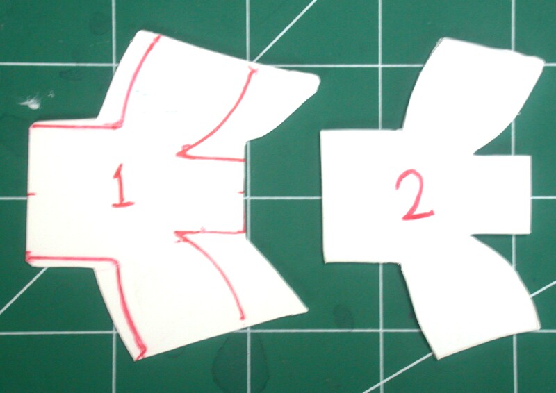 The deck extension (1) and the deck filler piece (2). The template for the filler piece was made with tracing paper. |
The deck extension from Step 3 is first bonded to the bottom surface of the Raider decking with polystyrene glue. The extension is positioned so that its perimeter aligns with the holes in th decking. Once the glue has dried, the Raider nose section can be bonded to the deck extension. The bottom surface of the nose section should be bonded to the extension with polystyrene glue. Allow the glue to dry thoroughly before proceeding to Step 6.
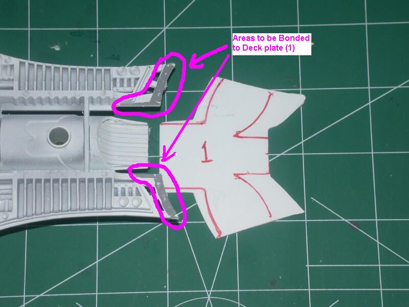 A bottom view of the Raider decking. The outlined areas will be bonded to the deck extension |
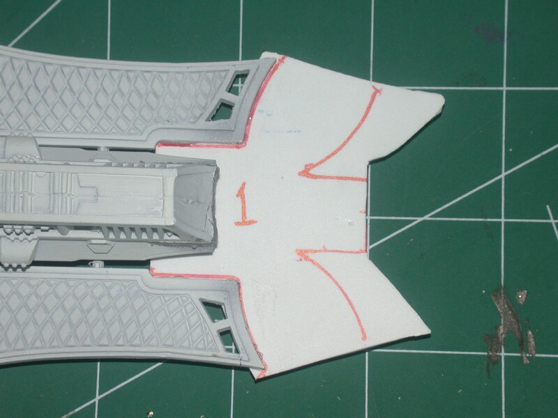 A top view showing the deck extension (1) glued to the decking. |
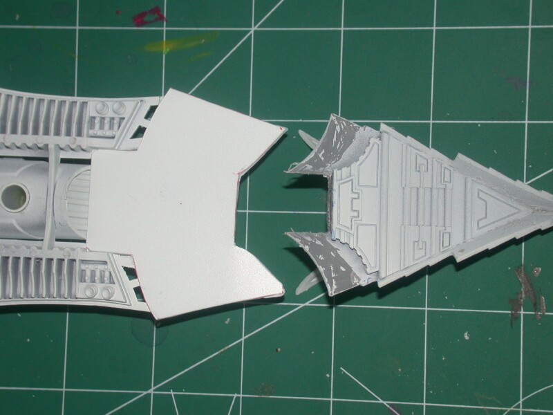 A bottom view of the raider decking, extension and nose. The outlined areas will be bonded to the deck extension |
The deck filler piece is placed on top of the deck extension and bonded in place with polystyrene glue. Once the glue has dried, any gaps around the deck filler piece can be filled with 5-minute epoxy. The epoxy serves two purposes. It fills the gaps and strengthens the joints between the filler piece and the Raider decking and nose sections. Epoxy can also be used to fill any gaps between the deck extension and nose section on the bottom of the Raider.
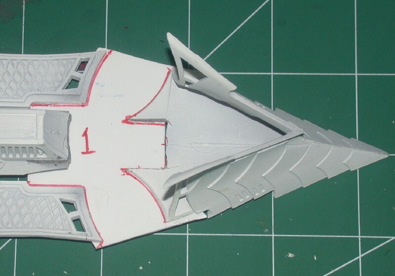 A top view of the assembled Raider decking, deck extension (1) and nose section. |
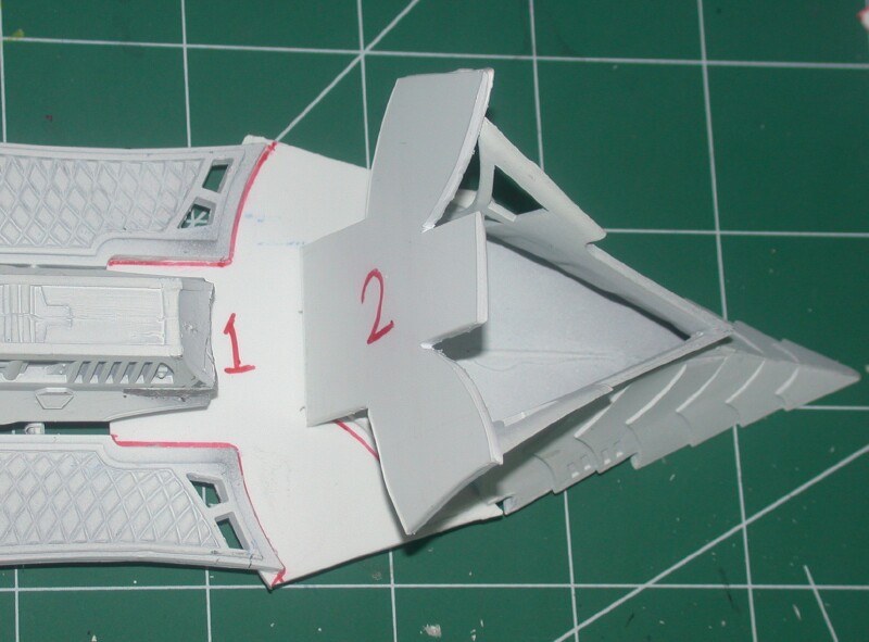 A view of Deck filler piece(2) being installed on top of the deck extension (1). |
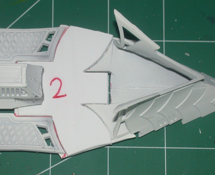 A view of the Deck filler piece (2) after it is bonded in place with polystyrene glue. |
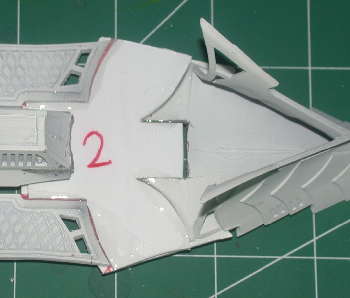 Any gaps between the Deck filler piece and the other components can be filled with 5-minute epoxy. |
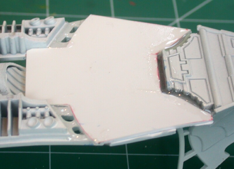 A bottom view of the deck extension. Any gaps can be filled with 5-minute epoxy. |
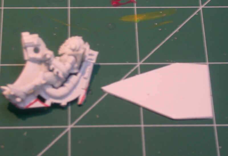
Since the driver for the Despoiler is mounted in a forward position, the tail section will need to be modified and the driver mounted on a flat base that fits in the nose section of the vehicle. The driver and seat are cut away from the normal Raider tail section as illustrated below. Save the remaining tail section as you will need it later.
A 5-sided, wedge-shaped base is made with some 0.030-inch polystyrene sheet. The base should be sized to fit in the nose section. The driver/seat are bonded to this base with polystyrene glue and positioned as far forwad in the nose section as possible. The legs of the driver may need to be bent or broken and re-glued to acheive the best fit.
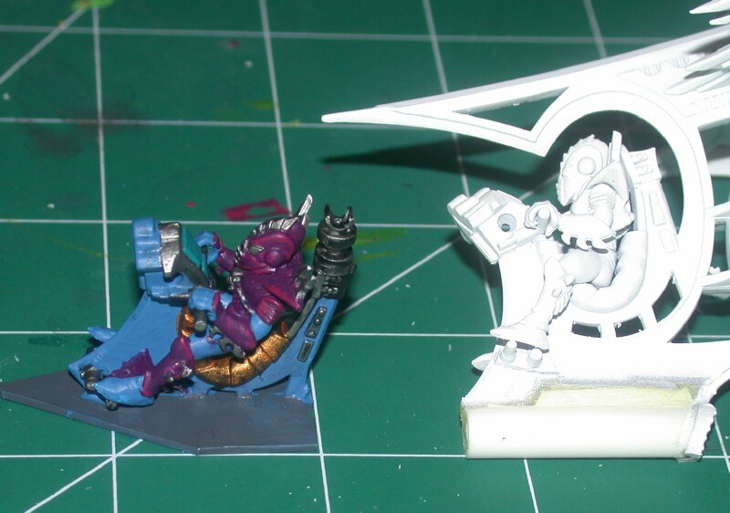 A view of a painted Despoiler driver mounted on a base and an unmodified Raider tail section |
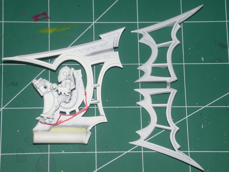 The top fin is removed from the tail section. The driver/seat are cut out of the tail section as denoted in red. |
 A view of the driver/seat and the 5-sided base plate. The driver/seat will be bonded along the center-line of the base plate. |
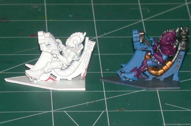 A view of the newly assembled driver/seat and plate. Note the crack in the driver's leg where it was broken and reglued. |
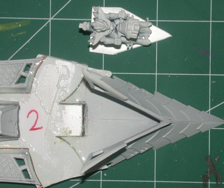 A top view of the driver and the nose section. |
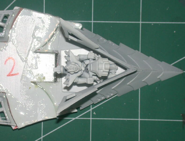 Another view showing the driver fitted as far forward in the nose section as possible. |
The nose section of the Raider has two large "railings" or extensions that project back from the the front cowling of the vehicle. These "railings" need to be removed to give the driver and gunner a clear field of view.
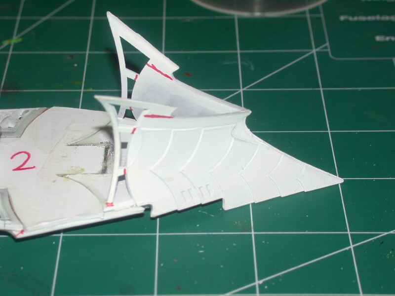 A view of the nose section and "railings." The areas to be cut are marked in red. |
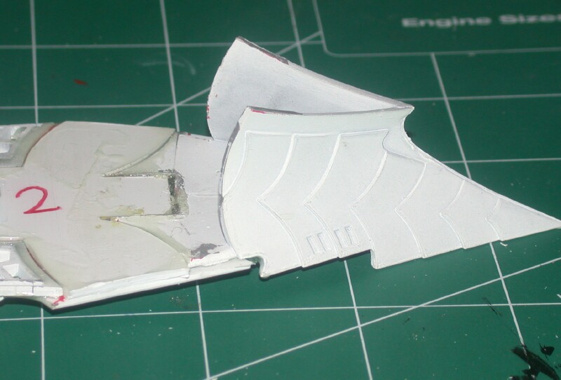 The nose section after it is trimmed. |
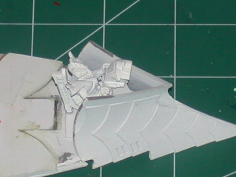 A trimmed nose section with the driver mounted in it. |
The gunner will be positioned in the nose section of the Despoiler behind the driver. He will be placed atop a raised platform so that his weapon fires over the head of the driver. The platform is essentially a rectangular box made with 0.030-inch polystyrene sheet. The length of the box is determined by the spacing between the Raider body and the back of the gunners seat (approximately 1.25-inches). The height of the box should be approximately 0.25-inches. The simplest way to make the box is to cut a strip of polystyrene that is the roughly 1.25 inches wide and several inches long. This strip is then cut into two 1/4-wide side pieces and one 5/8-inch wide top piece. The side pieces are bonded to the top piece with polystyrene glue so that they form a U-shaped channel. After the glue has dried, the outline of the U-shaped channel is traced on another piece of polystyrene so that an end-cap can be cut. The end cap is bonded to the end of the U-shaped channel to form the box that is open on one side.
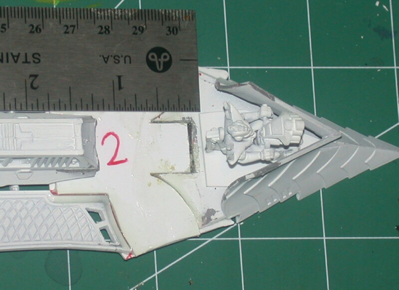 The length of the raised platform will be determined by measuring the distance between the driver and Raider body (approx 1.25") |
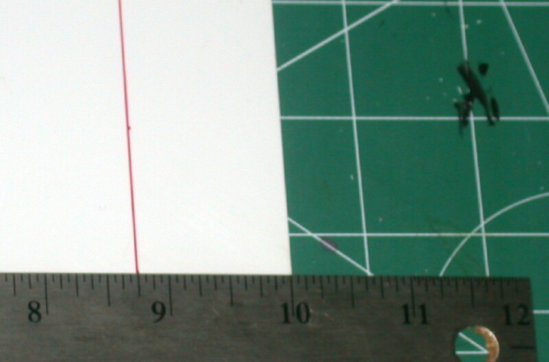 A sheet of 0.030-inch polystyrene sheet is marked and cut to make a strip that is approx. 1.25 inches wide and several inches long |
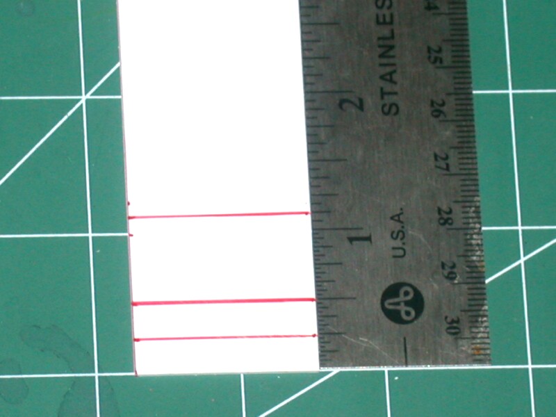 The polystyrene sheet strip is then marked and cut to make two side pieces and a top piece. |
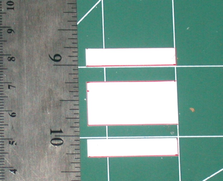 A view of the cut top piece between the side pieces. |
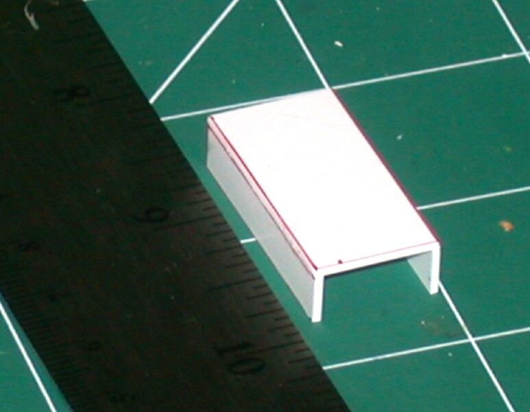 The sides are glued to the top piece with polystyrene glue so that they form a U-shaped channel. |
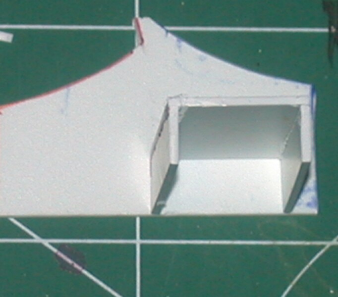 The outline of the U-shaped channel is traced on to some 0.030-inch polystyrene sheet. |
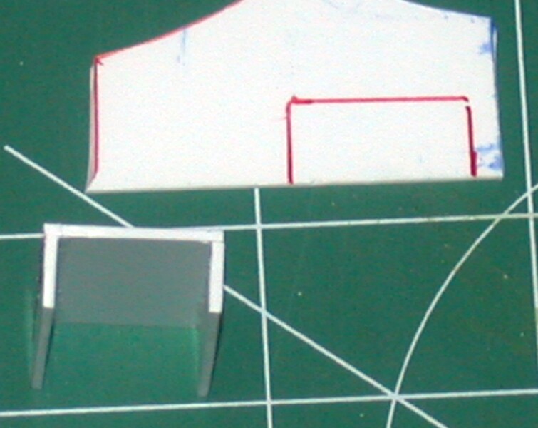 A view of the U-shaped channel and marked polystyrene sheet for the end cap. |
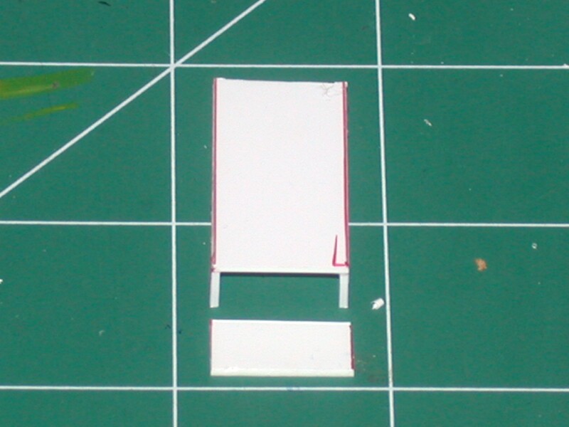 The end cap is glued to the U-shaped channel to complete the raised platform |
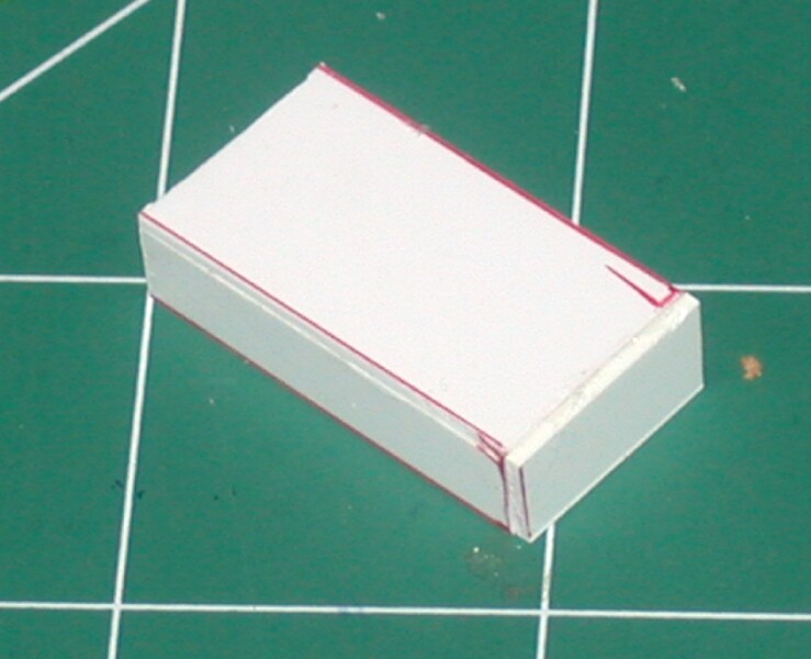 A view of the raised platform after it is completed. |
Now that the raised platform for the gunner is completed, the mounting for the gunner's weapon can be added to the back of the driver's seat. First, the raised platform is positioned on the tabletop so that it is immediately behind the driver. Next the gunner is place on top of the raised platform and positioned so that the gun mount is adjacent to the back of the driver's seat. The gun mount is then marked where it will be cut and glued to the back of the driver's seat. The gun mount is cut at this mark and the end is sanded or filed to match the top of the driver's seat. The top of the driver's seat can also be filed or sanded to better match the cut end of the gun mount.
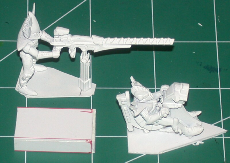 A view of the gunner, raised platform and driver. |
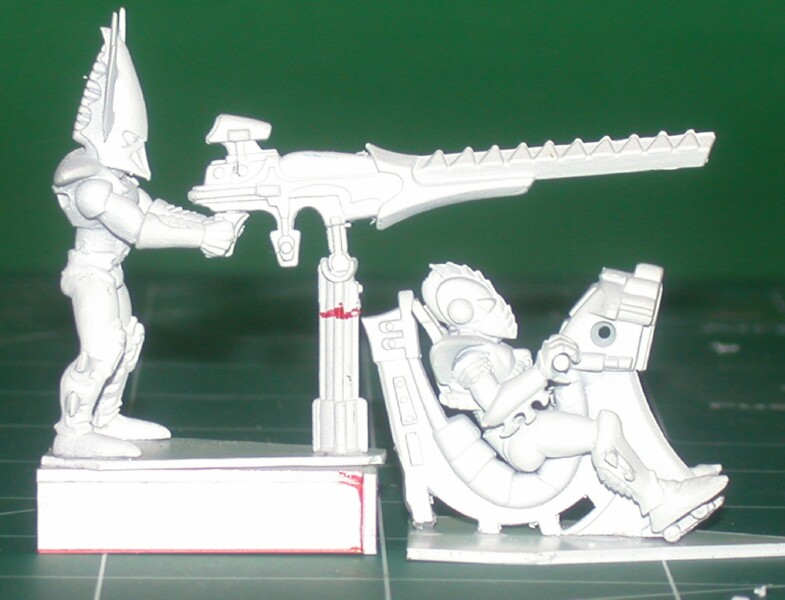 The raised platform is positioned behind the driver and the gunner is place on top. The red line denotes where the gun mount will be cut and glued to the driver's seat |
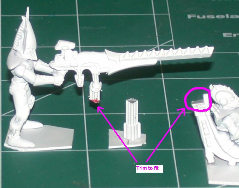 The gun mount has been cut to fit with the top of the driver's seat. The driver's seat has been sanded flat (see highlighted area) to mate with the gun mount. |
Since the Despoiler comes equipped standard with a Horrorfex instead of a dark lance, the gunner's weapon will need to be modified. For my Horrorfex I shorten the dark lance and add a demonic head to the front of the weapon. The demonic head comes from the Games Workshop Chaos tank sprue although another head could be substituted. Plastic putty is used to fill any gaps in the modified weapon and the whole is sanded smooth..
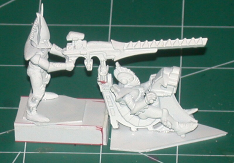 A view of the assembled gunner, raised platform and driver. |
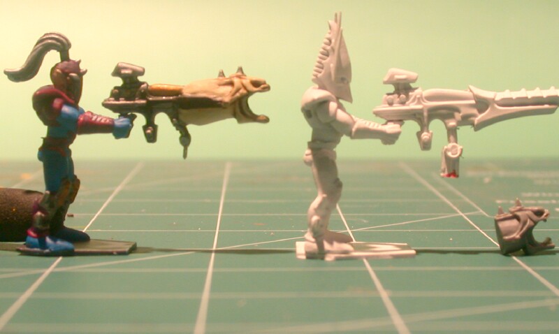 A completed gunner with Horrorfex (left) stands next to the gunner that will be modified.. The demonic head is on the right. |
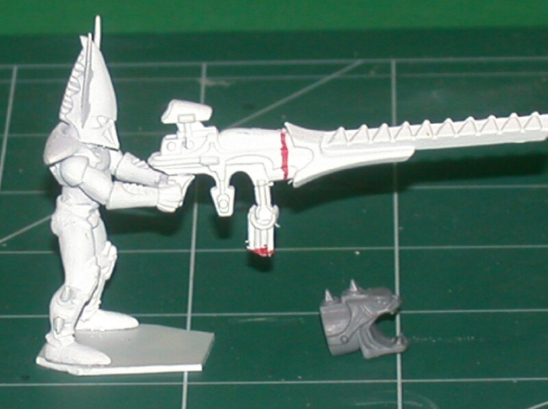 The dark lance is shortened by cutting off the barrel as marked with the red line above. |
 The dark lance has been shortened and the cut end sanded flat to fit the demonic head. |
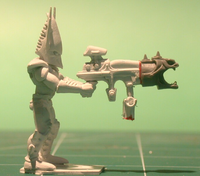 The demonic head is glued to the cut end of the dark lance. |
 A view of the completed driver and gunner assembly. |
The raised platform for the gunner can now be glued on to the deck filler/extension that was added in Steps 5&6. The platform should be aligned so that it is centered along the center-line of the raider. The open end of the raised platform should be positioned so that it mates with the end of the Despoiler body where the nose section was cut away. Polystyrene glue can be used to bond the raised platform in place. Any gaps between the raised platform and Despoiler body can be filled with plastic putty and sanded.
| Hosted by www.Geocities.ws
|
