WARNING FCC REQUIRES ALL FM TRANSMITTERS OVER 1 WATT BE LICENCED
Well the transmitter was a fun weekend project. Well a weekend includs building the box and antenna as well. The total price for parts came to be about $40. However, all of the parts used in the box and a some on the board were from my inventory (Proof that it is a good idea to collect, and hoard roadside electronics). The total price that I payed to Mouser was $29.17 that pretty much covered all of the board with exception of the resistors and a couple of capacitors. The rest was the box, some metal scraps used for the frame, connectors, 2-pole switch, and a bicolor LED.
When I plugged it in I was pretty suprized to see it work seeings how my soldering job was...interesting. Some of the tracks came off, and one of the trimmer's lead fell off. However despite this it is working pretty well despite the wrong coax and a shoddy antenna. However once I get it tuned it doesnt come up after I turn it on agian, and it is a real pain to tune.
Here is the board layout...
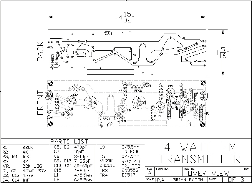
THIS IS NOT TO SCALE
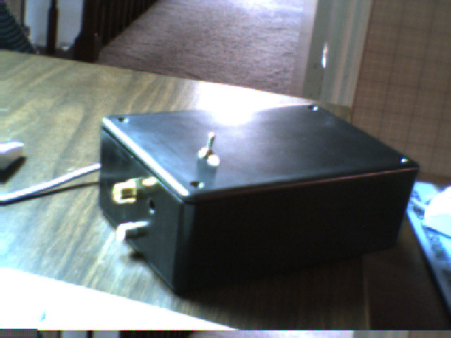
This is it all closed up...
This is an over head picture (opened)...
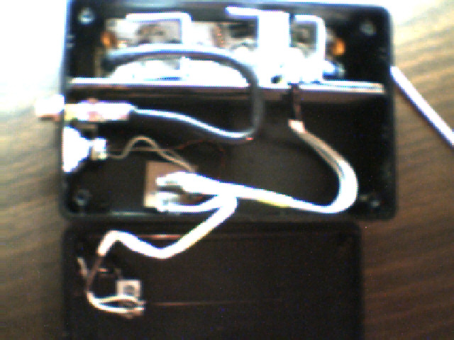
the bottom is the lid, and the top is the box. In the bottom side of the box are the connectors and a carrier board that the cover and the transmitter plug into. the rest of the bottom is open for future accessories. The top is the transmitter, which is fastened to a frame. The frame is held by the tracks in the side of the box, and can be easily removed for easy access. The board itself is fastened to the frame by two screws, and can be seperated from the frame
Here is the frame with the transmitter...
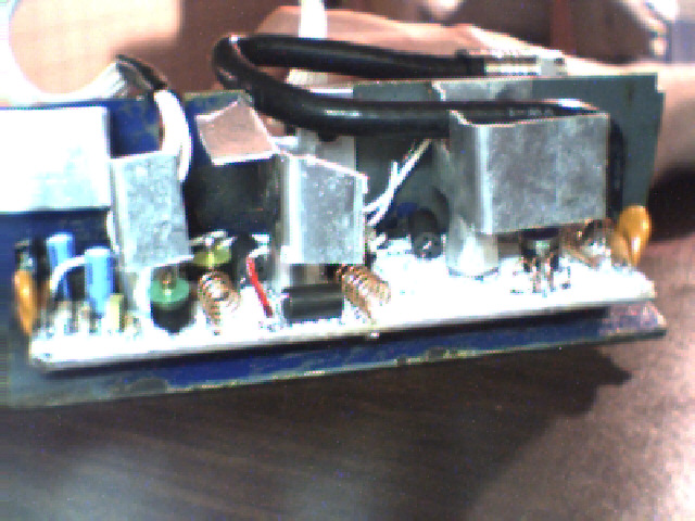
The big gray blobs are the heat sinks.
Other than what is shown on the diagram, heat sinks are supposedly needed on only the last two transistors, but I have had all three get significantly hot, and the last one burnt me. The heat sinks are very important, don't start it up without them unless you don't mind buying another transistor.
The connections are as listed:
1 Audio Ground
2 Audio Input
3 V-
4 V++
5 Antenna Ground
6 Signal
If you have any questions, post a message at Aaron Cake's Forum. Just include the name "BEatonNO1" in the heading.
If that doesn't work try [email protected]
This circuit was found HERE
, and it is higly suggested that you go there before starting this project
Back