![]()
Balanced microphone tube preamplifier
Mic-preamp
PCB Mic-preamp
PCB layout
Back to Welcome
Few years ago, my friend have told me about some young, perspective musicians and their intentions to run own recording studio, record albums on their equipment. About recording studios here I don't want say much, only that they are strange mix of 90% unneeded things and 98% incompetent people. They run businesses, and they have little or no interest in sound. Computers, midi, expanders, limiters, all this junk placed in their studios for god-know-why reasons (they forgotten for sure why and when they bought it), and final products is what we must listen and call it music. But he have told me that they want tubed equipment, and I agreed to meet them.
Guys was really young, and play good music too, and after clearing what they really need, I accepted to design a balanced, tube microphone preamplifier for electrostatic (1"diapraghm) mike, and five channel low noise, state of the art solid state microphone preamplifier.
Today, they are THE most popular band in Croatia. They won all prizes (best debut album of year, best song and best new band) for year 1997. Since then, they recorded two albums and get international awards. Numerous demos and albums are recorded in his studio. And sonic fingerprint of my preamplifiers is on every single piece they have done, and, for sure, recognized by everyone, defined as "best vocal ever recorded" (this girl really sings), or "clarity and space" from bass to highest octaves. Band is named "JINX".

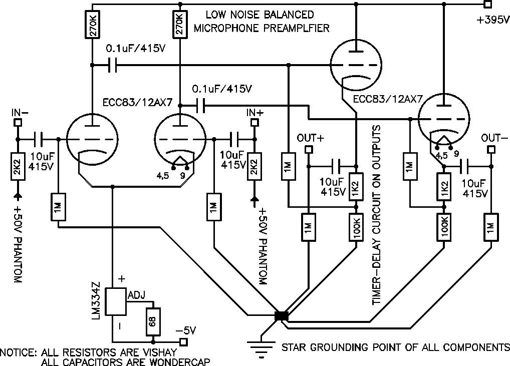
CIRCUIT is simple, for known reasons: signal processing must be minimized ; and if we need less components, we could buy best available. Input stage is differential amp with ECC83/12AX7, supplied from LM334 current source. For safer low frequency roll-off, second stage is NOT directly coupled to output cathode follower. But, you must use best coupling capacitors in whole circuit, to preserve musical information.
Phantom voltage regulation, filament regulation, negative voltage regulation and timer/delay circuits are present on PCB. Main power supply (transformer, raw DC supply's, and B+ supply/regulation MUST be placed in separate housing. Multivoltage power supply will be presented on special page.
This preamplifier INVERTS PHASE, so, maybe you need to re-invert them (as is on schematic) or use phases inverted- simply change + and - outputs.
Mic-preamp PCB Mic-preamp component layout on PCB Tubed line stage
This document maintained by
Drazen
Zeman. E-mail us.
Material Copyright © 1999.
DRAZEN ZEMAN