Skype headset adapter (2.5mm to 3.5mm jack, mobile phone to PC adapter)
1.0: CDG 15-Jan-2006
1.1: CDG 23-Jan-2006
1.2: CDG 14-Feb-2006
1.3: CDG 01-Apr-2006
These pages are about making an adapter to connect a mobile phone headset with a 2.5mm plug to a laptop PC with two 3.5mm jack sockets.
Warning: while the converter described below works for every headsets I have tried with my laptop, there is no guarantee that it will work for all computers and all headsets. There is some chance that by using this type of converter you will fry your headset and/or the audio system of your computer. Only you know how good your electronic construction skills are and how much risk you are prepared to take with your computer and headset. If in doubt then play it safe and wait for an innovative company to start making suitable headsets or adapters...
Note: The article relates to PC "headphone" and "microphone" connections and not "line-in" and "line-out". Sometimes "line-out" and "headphone" may be the same but "line-in" and "microphone" are electrically different.
Why?
Have you tried Skype peer-to-peer telephony? Its great and its free! It works surprisingly well from a laptop's built in microphone and speakers but having a headset really improves the sound quality. There are lots of headsets for PC but most of the reasonably priced ones seem to be targeted at games. These don't work well for travel because the head-loop and microphone boom are ungainly and don't squash well into a laptop bag.
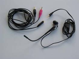
Recently I tried to buy a compact ear-bud type PC headset that I could easily carry with me when traveling. I checked out the local electronics stores and many times thought I'd found a perfect headset only to discover that it only came with a 2.5mm plug for mobile phones. Whenever I asked about headsets with 3.5mm plugs I was pointed to the PC headsets which, sure enough, were bulky and designed for games.
Finally I got a break. I found a compact headset that came with a converter cable for connecting to a PC. The only downside was that it cost $40, two or three times the as much as the other headsets. I bought it anyway and have to say I got a really nice headset! I also figured I could easily reverse engineer the converter, build my own and use $10 headset next time. I wrote up the information below so you won't have to spend $40 to find out the same thing.
A quart into a pint pot
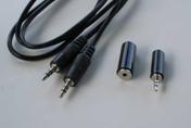
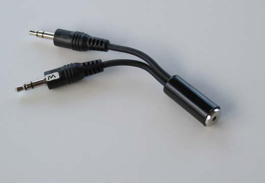
The common mobile phone headset connection is a single 2.5mm jack plug with 3 conductors (left of the photo). It's easy to buy the right ones as the packaging will say something like "2.5mm plug, not for Nokia". Headsets for some Nokia phones have a 4-condictor 2.5mm plug. They are the wrong ones for this project.
PC's, on the other hand, have two 3.5mm jack plugs with 3 conductors each (right side of photo).
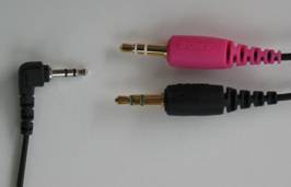
As you may have noticed the math doesn't work out well for the number of conductors. The phone plug has 3 conductors and the PC plugs have 6 between them. How can we make 6 conductors fit into 3? Read on...
PC inputs and outputs
The following diagram shows the connections a PC's headphone and microphone sockets.
As you can see the tip (1) of the headphone socket carries the left channel, the ring (2) carries the right channel and the sheath (3) is ground.
For the microphone things are a little more complicated. PC's use electret microphones with small built in amplifiers. Power has to be supplied for the amplifier and this is supplied though the ring (2) via a resistor to limit a short circuit current. Vmic is typically between 5V and 3.3V (4.2V on my Dell D600). The tip (1) carries the microphone signal to the PC and the sheath (3) is ground.
We need to reduce these 6 connections down to 3 on the cell phone plug. An easy start is to connect the two grounds together. In addition phone headsets are mono so we only need one of the output channels. But we're still one connection over budget. This is solved by using the wire carrying the microphone signal to the PC to also carry power from the PC to the microphone. It works because the PC input is A/C coupled -- Note the capacitor in the PC input path. This removes the Vmic DC offset from the signal coming back from the microphone before it goes into the PC's input amplifier.
Commercial Adapter
With my trusty multimeter I buzzed out the connection in the commercial 2.5mm to 2x 3.5mm adapter that came with the $40 headset. Along the way I checked for any significant resistances or capacitances between connectors but didn't find any. The connections are shown in the diagram below:

As you can see from the diagram the commercial adapter has the PC left and right outputs are shorted together. I've used the adapter with no discernable ill effects on my PC so I guess the audio output amplifiers used in laptops are sturdy enough internal limiters and cut-offs to keep the magic smoke in, even when they are abused. But, I was brought up to consider it bad form to short outputs together and as a result I used the circuits in the next section.
Home grown Adapter v1
The circuit below is the first one I used in a home grown adapter. It avoids shorting outputs together by simply leaving the right channel unconnected.
You might think it would be a problem to just loose one of the channels but it isn't. Telephone audio is mono and I've used this adapter a lot with Skype with no problems at all because identical audio goes to both channels. Its no good for listening to listening to iTunes though.
Home grown Adapter v2
Anyone that's not comfortable with just leaving out the right channel unconnected might prefer the version-2 scheme below. Instead of shorting the outputs together they are mixed though two resistors. I've found values for the resistors of between 20R and 100R work well, at least with the headsets I've tested. At the 100R end of the scale there is a noticeable drop in volume.
One of my test headsets has an impedance of around 16 ohms at 1KHz so resistor values of 20R shouldn't strain the output amplifiers too much.
Parts
The first prototype I spent about $4 on two 3.5mm stereo (3 conductor) plugs and a 2.5mm stereo (3 conductor) socket. Its show below. Note the label needed to tell which plug should be connected to the microphone.
In addition to the basic parts a 2.5mm plug is needed to help with testing all the connection before attaching a headsets or computer.
This adapter worked quite well but the wiring was just unshielded flex twisted together. This resulted in some faint noise pick up from the computer. Screened cables were needed in the next versdion...
To reduce the fiddle work of soldering screened cable I decided to buy a pre-made 3.5mm-stereo-plug to 3.5mm-stereo-plug cable and cut it in half. This eliminates two thirds of the tricky soldering. Plus, the screened cable is included in the cost which was only only $1 more than the two unattched plugs.
Final parts list:
- Stereo 3.5mm plug to plug audio cable (3' was the shortest I could find)
- 2.5mm Stereo Jack
- 2.5mm Stereo Plug (for testing)
Construction details
If, after reading the warnings above, you'd like to try to make an adapter then the following instructions should help. The minimum tools that are needed are fine pliers and cutters, a multi-meter and a good soldering iron. A small construction vice, to hold things while soldering, also helps a lot.

- If you haven't got experience soldering get help from someone that does! Solder gives off noxious fumes - Read the instructions for your soldering equipment.
- Cut the plugs off of the cable leaving about 2" to 3" (8cm) of cable on each plug.
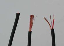
- Strip about 1/2" (1.5cm) of the outer insulation to reveal the metal mesh sheath. Pull the sheath away from the inner wires and twist it together. Then strip ¼" (4mm) of insulation from the inner wires. (see below)
- Use a multimeter to figure out which wires connect to which parts of the plug. The sheath must connect to the sheath of the plug. If this isn't the case you've got a very odd cable and you should probably discard it and start again.
- After working out the plug connection use the diagrams above to figure out where you'll have to hookup wires. The mono adapter (v1) is much easier to make. If you are building the mixing adapter (v2) then it unlikely that you'll be able to squeeze the resistors into the 2.5mm jack cover so you'll have to improvise some way to hook them up externally. A cable bulge covered with heat shrink insulation works well.
- Before you start of solder, thread the wires for the two plugs through the cover of the 2.5mm jack.
- Solder up the connections and screw on the 2.5mm jack cover.
- This is the most important step: Plug in the spare 2.5mm plug, get a multimeter and check that every connection you intended to make is made and that no conductors are unintentionally shorted together or shorted to ground.
- It is a good idea to mark the microphone plug clearly to avoid plugging your delicate microphone into the headphone output.
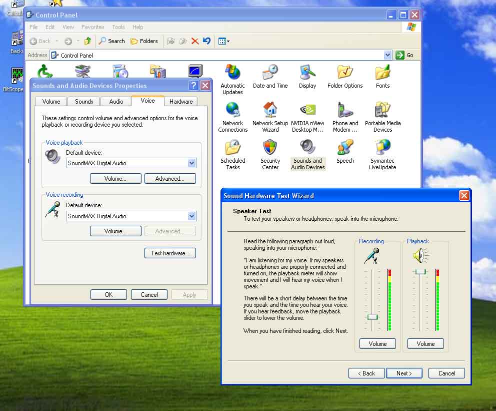
Testing
I used the microphone test feature in Windows XP installation to test the adapter. (In control panel click "Sound and Audio Devices"-> "Audio" tap -> "Voice" -> "Test Hardware" (wait) ->"Next".
If you have Microsoft Office installed then "Control Panel"->'Speech"->"Speech recognition"->"Configure Microphone" is another excellent way to evaluate your headset.
Then of course there is the Skype test call that will play back 10 seconds of whatever you say to it.
Final word
Maybe soon the headset manufacturers will start selling cheep adapters but until then I hope this page was of some help. Please drop me a note (cuthbertgrubb at yahoo.com) if you construct an adapter and find it does or doesn't work with a particular headset or PC. I'll start to publish a compatibility list from the responses.
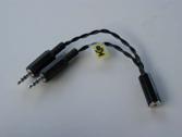
Here's the Version-2 adapter that I use day-to-day:
.
For anyone not keen on soldering iron burns Andre T. sent email to say he found these for sale at cyberguys.com (search for “2.5mm Mobile Headset To Pc Converter”)
Mark C. suggested using a band of colored heat shrink tubing around the cable of the mic or the phone jack to make it easy to tell one from the other. Its a good idea - as you can see I used a little white paint on the plug body itself but the head shink tube on the cable is probably a lot neater and more robust.
email cuthbertgrubb at yahoo.com.

This work is licensed under a Creative Commons Attribution-NonCommercial-ShareAlike 2.5 License.