This is copied from
http://www.howstuffworks.com/digital-clock.htm
|
How Digital Clocks Work |
Chances are that in your
bedroom you have a digital clock beside your bed. Have you ever looked at it in
the morning and thought, "I wonder how this thing works?" On the
morning that you ask that question you will be very glad to have this edition
of How Stuff Works
nearby, because this edition explains exactly how a digital clock (or
wristwatch) works. In fact, this edition of HSW even shows you how to build
your own! To understand how a digital clock works you have to get inside and
see exactly what is going on, and in order to do that you will learn everything
you need to build one yourself for about $30. So let's get started!
The Basics
If you have read the How Stuff Works
article on pendulum clocks,
you know that all clocks (regardless of technology) have a few required
components:
- A source of power to run the clock. In a pendulum clock the weights
or the springs handle this role.
- An accurate timebase that acts as the clock's heartbeat. In a
pendulum clock the pendulum and escapement handle this role.
- A way to gear down the timebase to extract different components of
time like hours, minutes and seconds. In a pendulum clock gears serve this
role.
- A way to display the time. In a pendulum clock the hands and face
serve this role.
A digital clock is no
different. It simply handles these functions electronically rather than mechanically.
So in a digital clock there is an electrical power supply (either a battery or
120 volt AC power from the wall). There is an electronic timebase that
"ticks" at some known and accurate rate. There is an electronic
"gearing mechanism" of some sort - generally a digital clock handles
gearing with a component called a "counter". And there is a display,
usually either LEDs (light emitting diodes) or an LCD (Liquid Crystal Display).
High Level View
Here is a quick overview of the
components of a digital clock at a high level.
At the heart of the clock there is a piece
that can generate an accurate 60 hertz (60 oscillations per second) signal.
There are two ways to generate this signal:
- The signal can be extracted from the 60 hertz oscillations in a
normal power line.
Many clocks that get their power from a wall socket use this technique
because it is cheap and easy. The 60 hertz signal on the power line is
reasonably accurate for this purpose.
- The signal can be generated using a crystal oscillator.
Obviously any battery-operated clock or wristwatch will use this technique
instead. It takes more parts but is generally much more accurate.
The 60 hertz signal is
divided down using a "counter". When building your own clock a
typical TTL part
to use is a 7490 "decade counter". This part can be configured to
divide by any number between 2 and 10, and generates a binary number as output. So
you take your 60 hertz time base, divide it by 10, divide it by 6 and now you
have a 1 hertz (1 oscillation per second) signal. This 1 hertz signal,
obviously, is perfect for driving the "second hand" portion of the
display. So far the clock looks like this in a block diagram:
Many
clocks do not display seconds. In that case the same
divide-by-10-then-divide-by-6 sequence is used to generate a signal with a
1-cycle-per-minute freqency. If the clock does display seconds then the output
of the counters needs to drive a display. The two counters produce binary numbers. The
divide-by-10 counter is producing a 0-1-2-3-4-5-6-7-8-9 sequence on its
outputs, while the divide-by-6 counter is producing a 0-1-2-3-4-5 sequence on
its outputs. We want to display these binary numbers on something called a
"7-segment display". A 7-segment display has 7 bars on it, and by
turning on different bars you can display different numbers:
To
convert a binary number between 0 and 9 to the appropriate signals to drive a
7-segment display, you use a (appropriately named) "binary number to
7-segment display converter". This chip looks at the binary number coming
in and turns on the appropriate bars in the 7-segment LED to display that
number. If we are displaying the seconds, then the seconds part of our clock
looks like this:
The
output from this stage oscillates at a frequency of one-minute-per-second. You
can imagine that the minutes section of the clock looks exactly the same.
Finally the hours section looks almost the same, except that the divide-by-6
counter is replaced by a divide-by-2 counter.
Now
there two details left to figure out if you are building a real clock:
- The clock as designed here does not understand that, at 12:59:59 it
is supposed to cycle back to 1:00. That is a messy little problem, and
there are a couple of ways to solve it. One technique involves creating a
little bit of logic that can detect the number 13 and reset the hour
section back to 1 (not zero). Another technique involves using an adder. For
our purposes it is easier to deal in military time, because military time
includes a zero hour...
- We need a way to set the clock. Typically this is handled by gating
higher-than-normal frequencies into the minutes section. For example, most
clocks have "fast" and "slow" set buttons. When you
press the "fast" button, the 60 hertz signal is driven straight
into the minutes counter. When you press the "slow" button a 1
hertz signal is driven into the minutes section. There are other
techniques possible, but this one is the most common.
Now let's see what we have
to do to build a real clock!
Building Your Own
Digital Clock
The best way to understand the different
components of a digital clock and how they work together is to actually walk
through the steps of building your own clock. Here we will build just the
"seconds" part of the clock, but you can easily extend things to
build a complete clock with hours, minutes and seconds. To understand these
steps, you will need to have read the How Stuff Works articles on Boolean logic and Electronic gates.
In particular the Electronic
gates article introduces you to TTL chips, breadboards and power supplies.
If you have already played around with gates as described in that article, then
the description here will make a lot more sense.
The first thing we need is a power supply.
We built one in the How Stuff Works article on Electronic gates.
In that article we used a standard wall transformer that produced DC power and
then we regulated it to 5 volts using a 7805. For our clock we want to do
things slightly differently because we are going to extract our 60 hertz
timebase from the power line. That means that we want an AC rather than a DC
transformer, and we will use a part called a bridge rectifier to convert
the AC to DC. Therefore we need the following parts for the power supply:
|
Part name |
Jameco part # |
|
10 volt AC 400ma transformer |
147993 |
|
Bridge rectifier |
103018 |
|
7805 5 volt regulator (TO-220 case) |
51262 |
|
Two 470 microfarad Electrolytic Capacitors |
93817 |
|
5.1 volt Zener diode |
36097 |
|
1K ohm Resistor |
29663 |
A few notes on the parts used:
- The difference between the AC transformer we are using here and the
DC transformer we used in the article on gates is that the AC transformer
preserves the 60 hertz sine wave found in 120 volt household current. If
you want to use your volt-ohm meter to measure the voltage of an AC
transformer, be sure you use an AC voltage range rather than a DC range.
- We use the bridge rectifier to convert the AC to DC. One of the
terminals on the rectifier will be marked with a "+" and from
that you can find the minus and AC inputs. There is no polarity to an AC
transformer, so it does not matter which lead from the transformer you
connect to which AC lead of the rectifier.
- The 7805 and capacitors are wired just like they were in the How
Stuff Works article on Electronic
gates.
- The resistor and the zener diode extract a 60 hertz signal from the
transformer's sine wave. A diode is a one-way valve for electrons. A zener
diode is also a one-way valve, but in addition it passes electrons in the
other direction if they are above a certain voltage. The zener diode
therefore turns a 10 volt sine wave into a clipped wave oscillating
between 0 and 5 volts. This is perfect for clocking the TTL counters. The
1K ohm resistor makes sure that the current to the zener diode is limited
so we do not burn out the diode. The diode will have a band painted on one
end - this band should be the end connected to the resistor.
Circuit Diagram
Here's a circuit diagram for the power
supply and time base:
As we saw in the article on electronic
gates, the power supply is the most difficult part! To create the rest of the
clock you will need:
- Some (at least 4) 7490 or 74LS90 chips
- Some (at least 2) 7447 or 74LS47 binary-to-7-segment converters
- Some (at least 20) resistors for the LEDs in the 7-segment
displays. 330 ohms would be fine.
- Some normal LEDs as seen in the Electronic
gates article.
- Some (at least 2) Common Anode (CA) 7 segment LED displays (Jameco
part # 17208 is typical).
- Breadboards, wire, etc. as seen in the Electronic
gates article.
The number of chips,
resistors and LEDs you need depends on how many digits you are interested in
implemeting. Here we will discuss only seconds, so the numbers of parts listed
as "at least" are correct.
The pin out of
the 7490
Let's look at the 7490 briefly to see how it
works. Here is the pin out:
The 7490 is a "decade counter",
meaning it is able to count from 0 to 9 cyclically, and that is its natural
mode. That is, QA, QB, QC and QD are 4 bits in a binary number and these pins
cycle through 0 to 9, like this:
QD QC QB QA 0 0 0 0 0 0 0 1 0 0 1 0 0 0 1 1 0 1 0 0 0 1 0 1 0 1 1 0 0 1 1 1 1 0 0 0 1 0 0 1
You can also set the chip up
to count up to other maximum numbers and then return to zero. You "set it
up" by changing the wiring of the R01, R02, R91 and R92 lines. If both R01
and R02 are 1 (5 volts) and either R91 OR R92 are 0 (ground), then the chip
will reset QA, QB, QC and QD to 0. If both R91 and R92 are 1 (5 volts), then
the count on QA, QB, QC and QD goes to 1001 (5). So:
- To create a divide-by-10 counter you first connect pin 5 to +5
volts and pin 10 to ground to power the chip. Then you connect pin 12 to
pin 1 and ground pins 2, 3, 6, and 7. You run the input clock signal (from
the timebase or a previous counter) in on pin 14. The output appears on QA,
QB, QC and QD. Use the output on pin 11 to connect to the next stage.
- To create a divide by 6 counter you first connect pin 5 to +5 volts
and pin 10 to ground to power the chip. Then you connect pin 12 to pin 1
and ground pins 6, and 7. Connect pin 2 to pin 9 and pin 3 to pin 8. Run
the input clock signal (from the timebase or a previous counter) in on pin
14. The output appears on QA, QB and QC. Use pin 8 to connect to the next
stage.
Creating the
second hand
Knowing all of this, you can easily
create the "second hand" of a digital clock. It looks like this:
In this diagram, the top two 7490s divide
the 60 hertz signal from the power supply down by a factor of 60. The third
7490 takes a 1 hertz signal as input and divides it by 10. Its four outputs
drive normal LEDs in this diagram. The fourth 7490 divides the output of the
third by 6, and its three outputs drive normal LEDs as well. What you have at
this point is a "second hand" for your clock, with the output of the
second hand appearing in binary. If you would like to create a clock that
displays the time in binary, then you are set! Here is a view of a breadboard
containing a divide-by-10 counter, a divide-by-6 counter and a set of LEDs to
display the output of the counters in binary:
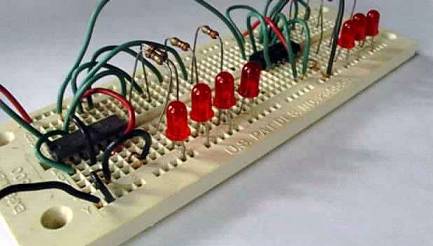
The wires entering the
picture from the left are power, ground and clock lines for the board. The left
counter is a 7490 set up to divide by 10, and the right one is another 7490 set
up to divide by 6. If you pack things tighter and do a neater wiring job you
can fit up to 4 counters on a single breadboard.
Displaying the
time as numerals
If you want to display the time as numerals,
you need to use the 7447s. Here is the pinout of a 7447, as well as the segment
labeling for a 7-segment LED:
![]()
You connect a 7447 to a 7490 like this:
- Provide +5 volts on pin 16 and ground on pin 8 to power the 7447
chip.
- Connect QA, QB, QC and QD from a 7490 to pins 7, 1, 2 and 6 of the
7447 respectively.
- Connect 330 ohm resistors to pins 13, 12, 11, 10, 9, 15 and 14 of
the 7447, and connect those resistors to the a, b, c, d, e, f, and g
segments of the 7-segment LED.
- Connect the common anode of the 7-segment LED to +5 volts.
You
will need to have the pinout for the specific LED display that you use so that
you know how to wire the outputs of the 7447 to the LEDs in the 7-segment
device. [Also, note that the 7448 is equivilent to the 7447 except that it
drives common cathode displays. Ground the common cathode of the LED in that
case.]
You
can see that by extending the circuit we can easily create a complete clock. To
create the "minute hand" section of the clock all that you need to do
is duplicate the "second hand" portion. To create the hour hand
portion you are going to want to be creative. Probably the easiest solution is
to create a clock that displays military time. Then you will want to use an AND
gate (or the R inputs of the 7490) to recognize the binary number 24 and use
the output of the recognizer to reset the hour counters to zero.
The
final piece you need to create is a setting mechanism. On a breadboard it is
easy to set the clock - just move the input wires to drive higher-frequency
signals into the minute hand section of the clock. In a real clock you would
use pushbuttons or switches and gates to do the same thing.
If
you happen to take your bedside clock or watch apart, one thing you will notice
is that there are probably not 15 TTL ICs inside. In fact, you may not be able
to find a chip at all. In most modern clocks and watches all of the functions
of the clock (including the alarm and any other features) are all integrated
into one low-power chip (in a watch the chip and display together consume only
about a millionth of a watt). That chip is probably embedded directly into the
circuit board. You might be able to see a blob of black plastic protecting this
chip. That one chip, however, contains all of the components we have discussed
here integrated into one very small device.
Now
you have a complete understanding of how digital clocks work! The next time you
look at the clock beside your bed or your digital wristwatch, you can do so
with a new respect for what is going on inside! If you would like to advance to
the next level and see how to build a digital clock with a microcontroller, see
the HSW
Microcontroller Article.