From web site
http://www.howstuffworks.com/car-computer.htm
The hyperlinks will take you back
to the original web site.
The article has been copied here just in case the web site is not up.
Each year, cars seem to get
more and more complicated. Cars today might have as many as 50 microprocessors
on them. Although these microprocessors make it more difficult for you to work
on your own car, some of them actually make your car easier to service.
Some of the reasons for this increase in the
number of microprocessors are:
- The need for sophisticated engine controls to meet emissions and
fuel-economy standards
- Advanced diagnostics
- Simplification of the manufacture and design of cars
- Reduction of the amount of wiring in cars
- New safety features
- New comfort and convenience features
Sophisticated
Engine Controls
Before emissions laws were enacted, it was possible to build a car engine without microprocessors.
With the enactment of increasingly stricter emissions laws, sophisticated
control schemes were needed to regulate the air/fuel mixture so that the
catalytic converter could remove a lot of the pollution from the exhaust. See How Catalytic
Converters Work for more details.
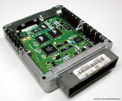
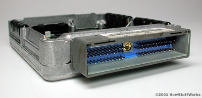
|
The computer from a Ford Ranger |
Controlling the engine is the most
processor-intensive job on your car, and the Engine Control Unit (ECU)
is the most powerful computer on most cars. The ECU uses closed-loop control,
a control scheme that monitors outputs of a system to control the inputs to a
system, to manage the emissions and fuel economy of the engine (as well as a
host of other parameters). Gathering data from dozens of different sensors, the
ECU knows everything from the coolant temperature to the amount of oxygen in
the exhaust. With this data, it performs millions of calculations each second,
including looking up values in tables, calculating the results of long
equations to decide on the best spark timing and determining how long the fuel injector is
open. The ECU does all of this to insure the lowest emissions and best mileage.
See How
Fuel-Injection Systems Work for a lot more detail on what the ECU does.
A modern ECU might contain a 32-bit, 40-MHz
processor. This may not sound fast compared to the 500- to 1,000-MHz processor
you probably have in your PC, but remember that the processor in your car is
running much more efficient code than the one in your PC. The code in an
average ECU takes up less than 1 MB of memory. By comparison, you probably have
at least 2 GB of programs on your computer -- that's 2,000 times the amount in
an ECU.
The processor is packaged in a module with
hundreds of other components on a multi-layer circuit board. Some of the other
components in the ECU that support the processor are:
- Analog-to-digital
converters - These devices read the outputs of some of the sensors
in the car, such as the oxygen sensor. The output of an oxygen sensor is
an analog voltage, usually between 0 and 1.1 volts (V). The processor only
understands digital numbers, so the analog-to-digital converter changes
this voltage into a 10-bit
digital number.
- High-level digital outputs
- On many modern cars, the ECU fires the spark plugs,
opens and closes the fuel injectors
and turns the cooling
fan on and off. All of these tasks require digital outputs. A digital
output is either on or off -- there is no in-between. For instance, an
output for controlling the cooling fan might provide 12 V and 0.5 amps to
the fan relay when it is on, and 0 V when it is off. The digital output
itself is like a relay.
The tiny amount of power that the processor can output energizes the
transistor in the digital output, allowing it to supply a much larger
amount of power to the cooling fan relay, which in turn provides a still
larger amount of power to the cooling fan.
- Digital-to-analog converters - Sometimes the ECU has to provide an analog voltage output to
drive some engine components. Since the processor on the ECU is a digital
device, it needs a component that can convert the digital number into an
analog voltage.
- Signal conditioners -
Sometimes the inputs or outputs need to be adjusted before they are read.
For instance, the analog-to-digital converter that reads the voltage from
the oxygen sensor might be set up to read a 0- to 5-V signal, but the
oxygen sensor outputs a 0- to 1.1-V signal. A signal conditioner is a
circuit that adjusts the level of the signals coming in or out. For
instance, if we applied a signal conditioner that multiplied the voltage
coming from the oxygen sensor by 4, we'd get a 0- to 4.4-V signal, which
would allow the analog-to-digital converter to read the voltage more
accurately (see How
Analog and Digital Recording Works for more details).
- Communication chips -
These chips implement the various communications standards that are used
on cars. There are several standards used, but the one that is starting to
dominate in-car communications is called CAN (controller-area
networking). This communication standard allows for communication speeds
of up to 500 kilobits per second (kbps). That's a lot faster than older
standards. This speed is becoming necessary because some modules
communicate data onto the bus hundreds of times per second. The CAN bus
communicates using two wires.
Advanced
Diagnostics
Another benefit of having a communications bus is that each module can
communicate faults to a central module, which stores the faults and can
communicate them to an off-board diagnostic tool.
This can make it easier for technicians to
diagnose problems with the car, especially intermittent problems, which are
notorious for disappearing as soon as you bring the car in for repairs.
This
page lists the fault codes stored in the ECU for various carmakers.
Sometimes, the codes can be accessed without a diagnostic tool. For instance,
on some cars, by jumping two of the pins in the diagnostic connecter and then
turning the ignition key to run, the "check engine" light will flash
a certain pattern to indicate the number of the fault code stored in the ECU.
Let's take a look at how microprocessors and
communications standards have made cars easier to build.
COMPUTER CODES for Honda Vehicles
This table may be used as a reference for interpreting your Honda vehicle's
computer messages.
If codes other than these are indicated, repeat self-diagnosis. If codes
reappear, substitute a known good ECM, and recheck codes. For 1985 through
1987. Note: OOOO all 4 lamps on, XXXX all 4 lamps off.
|
LED display |
Symptom
- Possible Cause for 1985 through 1987 Honda Vehicles |
|
OOOO |
Engine will not start - Check for disconnected control
unit ground connector. Also check for a loose connection at the ECU main
relay resistor. Possible faulty ECU. |
|
OOOO |
Engine will not start - Check for a short circuit in the
combination meter or warning light wire. Also check for a disconnected
control unit ground wire. Possible faulty ECU. |
|
OOOX |
System does not operate - Faulty ECU |
|
OOXO |
System does not operate - Faulty ECU |
|
OOXX |
Fuel-fouled spark plugs, engine stalls frequently - Check
for a disconnected MAP sensor coupler or an open circuit in the MAP sensor
wire. Also faulty MAP sensor. |
|
OXOO |
System does not operate - Faulty ECU. |
|
OXOX |
Hesitation, fuel-fouled spark plugs or engine stalls
frequently - Check for disconnected MAP sensor vacuum hose. |
|
OXXO |
High idle speed during warm-up, continued high or hard
starting at low temperature - Check for disconnected coolant temperature
sensor connector or an open circuit in the coolant temperature sensor wire.
Also faulty Coolant Temperature sensor. |
|
OXXX |
Poor engine response when opening the throttle rapidly,
high idle speed or engine does not rev-up when cold - Check for a
disconnected throttle angle sensor connector. Also check for an open circuit
in the throttle angle sensor wire. Also faulty throttle angle sensor. |
|
XOOO |
Engine dose not rev-up, high idle speed or erratic idling
- Check for a short or open in the crank angle sensor wire. Spark plug wires
interfering with the crank angle sensor wire. Also faulty crank angle sensor. |
|
XOOX |
Same as above (XOOO) |
|
XOXO |
High idle speed or erratic idling when very cold - Check
for disconnected intake air temperature sensor or an open circuit in the
intake air temperature sensor wire. Also faulty Intake Air Temperature
sensor. |
|
XOXX |
Continued high idle speed - Check for a disconnected idle
mixture adjuster sensor coupler or an open circuit in the idle mixture
adjuster sensor wire. Also faulty Idle Mixture Adjuster sensor. |
|
XXOO |
System does not operate at all - Faulty ECU |
|
XXOX |
Poor acceleration at high altitude when cold - Check for a
disconnected atmospheric pressure sensor coupler or an open circuit in the
atmospheric pressure sensor wire. Also faulty Atmospheric Pressure Sensor. |
|
XXXO |
System does not operate at all - Faulty ECU |
|
XXXX</FONT< td> |
Same as above (XXXO) |
|
CODE |
PROBABLE
CAUSE for Honda Vehicles 1988 and later. |
|
0 |
Faulty ECU (no signal) |
|
1 |
Oxygen sensor or circuit. |
|
2 |
Faulty ECU |
|
3 & 5 |
Manifold Absolute Pressure (MAP) sensor or circuit. |
|
4 |
Crank angle sensor or circuit |
|
6 |
Coolant temperature sensor or circuit |
|
7 |
Throttle angle sensor or circuit. |
|
8 |
TDC position/crank angle sensor or circuit. |
|
9 |
Crank angle sensor or circuit |
|
10 |
Intake air temperature sensor or circuit. |
|
11 |
No particular symptom shown or system does not operate -
faulty ECU |
|
12 |
Exhaust gas recirculation (EGR) failure |
|
13 |
Atmospheric pressure sensor circuit. |
|
14 |
Electronic air control valve (EACV) |
|
15 |
No ignition output signal - possible faulty igniter. |
|
16 |
Fuel injector circuit. |
|
17 |
Vehicle speed sensor or circuit (VSS) |
|
19 |
Lock-up control solenoid valve (automatic transmission) |
|
20 |
Electronic load detector - possible open or grounded
circuit in ECU wiring. |
|
21 |
VTEC spool solenoid valve circuit (Civic & Del-Sol) |
|
22 |
VTEC oil pressure switch circuit (Civic & Del-Sol) |
|
23 |
Knock sensor (Prelude) |
|
30 |
A/T control unit ECM fuel injection signal "A"
(Accord & Prelude) |
|
31 |
A/T control unit ECM fuel injection signal "B"
(Accord & Prelude) |
|
41 |
Heated oxygen sensor - heater circuit. |
|
43 |
Fuel supply system circuit (except D15Z1 engine) |
|
43 |
XX |
|
45 |
Fuel system out of range - rich or lean |
|
48 |
Heated oxygen sensor circuit (D15Z1 engine) |
|
50 |
Mass airflow sensor. |
|
61 |
Front oxygen sensor response slow. |
|
63 |
Rear oxygen sensor circuit voltage out of range. |
|
65 |
Rear oxygen sensor circuit malfunction. |
|
67 |
Catalyic converter efficency low. |
|
70 |
Automatic Transaxle problem. |
|
71 through 76 |
Cylinder misfires |
|
80 |
Insufficient EGR flow |
|
86 |
Engine coolant temperature sensor circuit. |
|
92 |
Evaporative emission purge valve problem. |
Disclaimer:
Use this as a guide, not a Bible. These codes are assumed current through 1997.
No warranties or guarantees as to correctness or fitness for use is stated or
may be implied
Easier
Design and Manufacturing
Having communication standards has made designing and building cars a little
easier. A good example of this simplification is the car's instrument cluster.
The instrument cluster gathers and
displays data from various parts of the vehicle. Most of this data is already
used by other modules in the car. For instance, the ECU knows the coolant
temperature and engine speed. The transmission controller knows the vehicle
speed. The controller for the anti-lock braking
system (ABS) knows if there is a problem with the ABS.
All of these modules simply send this data
onto the communications bus. Several times a second, the ECU will send out a
packet of information consisting of a header and the data. The header is just a
number that identifies the packet as either a speed or a temperature reading,
and the data is a number corresponding to that speed or temperature. The
instrument panel contains another module that knows to look for certain packets
-- whenever it sees one, it updates the appropriate gauge or indicator with the
new value.
Most carmakers buy the instrument clusters
fully assembled from a supplier, who designs them to the carmaker's
specifications. This makes the job of designing the instrument panel a lot
easier, both for the carmaker and the supplier.
It is easier for the carmaker to tell the
supplier how each gauge will be driven. Instead of having to tell the supplier
that a particular wire will provide the speed signal, and it will be a varying
voltage between 0 and 5 V, and 1.1 V corresponds to 30 mph, the carmaker can
just provide a list of the packets of data. Then, it is the carmaker's
responsibility to make sure that the correct data is output onto the
communications bus.
It is easier for the supplier to design the
instrument panel because he doesn't need to know any details of how the speed
signal is generated, or where it's coming from. Instead, the instrument panel
simply monitors the communications bus and updates the gauges when it receives
new data.
These types of communications standards make
it very uncomplicated for carmakers to outsource the design and manufacture of
components: The carmaker doesn't have to worry about the details of how each
gauge or light is driven, and the supplier who makes the instrument panel
doesn't have to worry about where the signals are coming from.
Smart Sensors
This technique is starting to be used on a smaller scale for sensors. For
instance, a traditional pressure sensor contains a device that outputs a
varying voltage depending on the pressure applied to the device. Usually, the
voltage output is not linear, depends on the temperature and is a low-level
voltage that requires amplification.
Some sensor manufacturers are starting to
provide a smart sensor that is integrated with all the electronics, along with
a microprocessor that enables it to read the voltage, calibrates it using
temperature-compensation curves and digitally outputs the pressure onto the
communications bus.
This saves the carmaker from having to know
all the dirty details of the sensor, and saves processing power in the module,
which otherwise would have to do these calculations. It makes the supplier, who
is most up on the details of the sensor anyway, responsible for providing an
accurate reading.
Another advantage of the smart sensor is
that the digital signal traveling over the communications bus is less
susceptible to electrical noise. An analog voltage traveling through a wire can
pick up extra voltage when it passes certain electrical components, or even
from overhead power lines.
Communication buses and microprocessors also
help simplify the wiring through multiplexing. Let's take a closer look
at how they do this.
Simplified Wiring
Multiplexing is a technique that can simplify the wiring in a car. In older
cars, the wires from each switch run to the device they power. With more and
more devices at the driver's command each year, multiplexing is necessary to
keep the wiring from getting out of control. In a multiplexed system, a module
containing at least one microprocessor consolidates inputs and outputs for an
area of the car. For instance, cars that have lots of controls on the door may
have a driver's-door module. Some cars have power-window, power-mirror,
power-lock and even power-seat controls on the door. It would be impractical to
run the thick bundle of wires that would come from a system like this out of
the door. Instead, the driver's-door module monitors all of the switches.
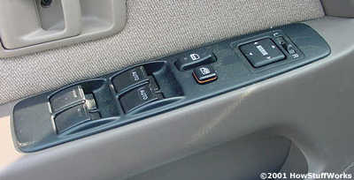
|
Doors with lots of switches are becoming more and
more common. |
Here's how it works: If the driver presses
his window switch, the door module closes a relay that provides power to the
window motor. If the driver presses the switch to adjust the passenger-side
mirror, the driver's door module sends a packet of data onto the communication
bus of the car. This packet tells a different module to energize one of the
power-mirror motors. In this way, most of the signals that leave the driver's
door are consolidated onto the two wires that form the communication bus.
The development of new safety systems has
also increased the number of microprocessors in cars. We'll talk about this in
the next section.
Safety Systems
Over the last decade, we've seen safety systems such as ABS and airbags become common on
cars. Other safety features such as traction-control and stability-control systems
are starting to become common as well. Each of these systems adds a new module
to the car, and this module contains multiple microprocessors. In the future,
there will be more and more of these modules all over the car as new safety
systems are added. At the 2001 North American Auto Show,
we saw Volvo's Safety
Concept Car (SCC), which showcased some of these upcoming safety features.

|
The Volvo Safety Concept Car |
New technology developed for this car allows
the vehicle's interior to adjust to the driver's body size and eye position.
Sensors scan the precise position of the driver's eyes and then adjust the
driver's seat to offer the best possible vision. The steering wheel, floor,
pedals and center console also adjust to a more comfortable position for the
driver.
The SCC includes active rearview mirrors and
rear bumper sensors that alert the driver to approaching traffic in the car's
blind spot. Rear-facing cameras also add to the driver's field of vision.
Adaptive headlamps monitor the car's speed and steering wheel movements and
adjust lighting accordingly. For example, at high speeds, light beams are given
a longer reach. The car is also equipped with an infrared light enhancer to improve
night vision.
Drivers moving outside of their lane will be
warned by the SCC's remain-in-lane technology. Forward-facing cameras monitor
the car's position in relation to the road's centerline and side-marker lines
for 20 meters ahead of the car. If the car begins to veer out of the lane, a
warning is sounded.
Each of these safety systems requires more
processing power, and is usually packaged in its own electronics module. But it
doesn't end there. In addition to more safety features, concept cars at the
2001 auto show were bursting at the seams with new convenience features, meaning
still more microprocessors.
Comfort and
Convenience
In coming years, we'll have all kinds of new features in our cars, and each of
these requires more electronics modules containing multiple microprocessors.
The Dodge Super8 Hemi
concept car showcased some of these technologies.
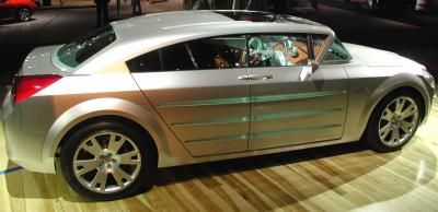
This concept car has such features as wireless Internet
access and voice control of many car functions, including audio,
climate-control, phone and even e-mail!
The rear passengers have individual LCD
touch screens so they can watch movies or access the Internet. The car has satellite radio and
can play MP3 music that you
transfer from your home stereo to the car while it is parked in the driveway or
garage.
It seems that there is no limit to how much
technology carmakers are going to pack into our cars. The addition of all these
electronic features is one of the factors driving carmakers to increase the
system voltage on cars from the current 14-V system to a 42-V system. This will
help provide the extra power these modules require.
From web site
http://www.howstuffworks.com/car-computer.htm
The hyperlinks will take you back
to the original web site.
The article has been copied here just in case the web site is not
up.