|
|
|
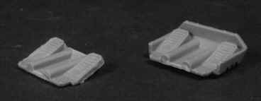
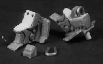
Attack bike conversion- page two. STEP 9 Fill the resulting gaping hole with epoxy putty. At least that's what I did, because the area will be virtually invisible once completed. However, you may wish to add detail to this area yourself. Go ahead. Knock yourself out. I just painted it black after it had dried. STEP 10 Trim the front sides of the floor plate so the front wheels fit a little more strongly.
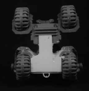
STEP 11 Glue the front wheels into place. The mating surface is quite small, but adequate. If you are not convinced, you could drill and pin the wheels in addition to gluing. Leave overnight to dry.
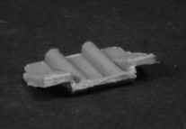
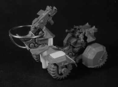
Cut and Glue a large diameter piece of plastic tubing to the center rear of the back plate, ensuring that the top is level with the top of the wheel pods. This is the turret mount. STEP 12 Add the Handle bars, Shield and bolters as normal. You can assemble and position the driver at this point, but don't glue him into position until you have finished painting.
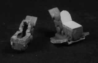
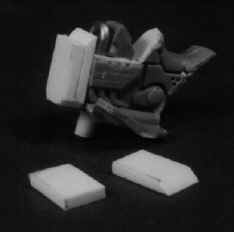
STEP 13 Grip the model firmly between your thumb and forefinger, and push it rapidly around the table top whilst shouting 'ZOOM VAROOM DAKKA DAKKA'. Failure to do this will cause the whole assembly to self destruct. Repeat at the end of each step, or as often as possible. Careful not to frighten the cat. STEP 14 - Turret. Begin by cutting and shaping the remaining floor pan as shown in the picture. This is a little tricky, but NOT essential. I just looks better this way.
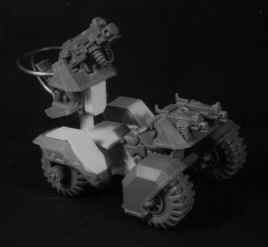
STEP 15 Trim the remaining seat/ engine by removing the fuel tank and forks as indicated. Shave off the engine block detail while you're at it. Cover the resulting hole with plastic card, (don't forget the back) then glue the assembly to the (trimmed) floor pan.
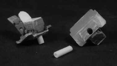
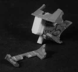
STEP 16 Drill a hole Under the front center to receive a short length if tubing. The tubing should fit snugly into the turret support already modelled onto the back of the buggy.Leave approximately 5mm protruding from the turret base, and ensure that everything is straight and level.
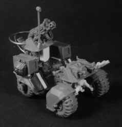
STEP 17 Bend a short section of aluminium wire and insert it into drilled holes in the top front of the turret as shown. This is the heavy weapon mount, it should protrude about 5mm Also, if you like, cut and trim the view screen from the remaining handlebars and glue that on as well.
STEP 18 Cut two pieces of 2mm plastic card , one 7 x 12mm, the other 7 x 14mm. Bevel one end of the longer piece to a 45 degree angle and glue to the back of the shorter one. Glue this to the front of the turret assembly.
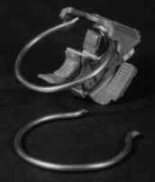
STEP 19 Trim the headlight and all detail from the rear of the remaining gunshield, and glue into place, making sure that it is level and parallel to the base. STEP 20 Shape and fit the safety ring to the rear of the gunshield. Use Superglue. I used an inside diameter of about 25mm (1"), though this is not critical. Drill a hole in the lower back of the turret and fit the support rail. This is a bit trial and error, just do your best.
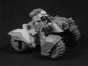
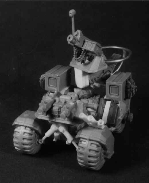
STEP 21 Fit heavy weapon and crew. You will have to covert the gunners arms to make him look right, but that's not too difficult.
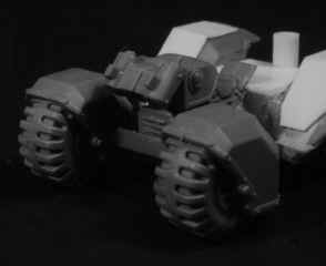
ALL DONE. The rest all just optional detail, added as you choose. I filled the area behind the driver with leftover bolters, auspex and assorted odds and ends. The shock absorbers and smoke launchers were made from plastic card and rod, and the Jerry cans and other equipment came from 35th scale military kits (mostly Tamiya).
|