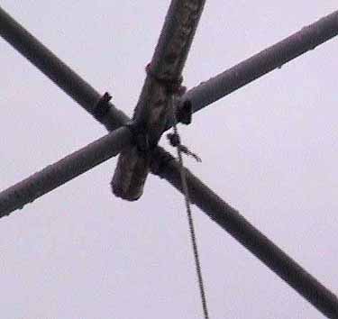
| Here is a 2 element quad which is light-weight in construction, yet can withstand strong winds and be an excellent DX-ing antenna. Having used a vertical antenna for many years, my first quad antenna was a totally new experience. It brought "life" into the radio and within a short period, new countries or prefix's became an everyday occurrence. When constructing quad antennas, much is left to the initiative of the home builder as to how he goes about it. There are a number of different ways to achieve similar results. The "spider" section of the quad, that which supports the arms, can be very difficult for someone with limited tools and budget. Commercially made ones, if available, are expensive to purchase. However, here is a very simple way of doing it and requires little effort or skill. The boom and cross arms are made of aluminium tubing. For the boom section we use 30mm (min.) and the cross arms can be 15mm. These are held in place by small U-bolts. To prevent any movement, 5 mm deep cuts are made in the boom and slightly depressed to hold the cross arms, and to prevent any twisting sideways. When the U-bolts are tightened, the cross arms should remain securely in place. (See Fig. 2 & Fig. 2a) |
 |
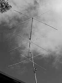
| Fig. 1 |
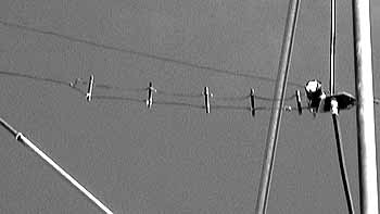
| The support arms are fixed in place by u-bolts, side by side and at 90 degs to each other as in Fig. 2 & 2a. These aluminium supports need only be about 50cm long. The ends have a 15mm cut (Fig. 3 & 3a) which will give a secure hold on the wooden rods when the hose-clip is tightened. In Fig. 1 we see the complete set-up of a 2 element horizontally polarized quad. |
 |
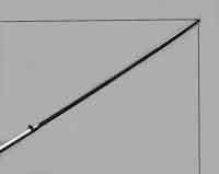
| Fig.2 |
| Measurements for Driven Element: Frequency: 27.400 MHz 27.300 MHz 26.300 MHz Wave-lenght = 1117.971cm 1122.065cm 1164.730cm each side = 279.493cm 280.516cm 291.183cm Each spreader = 197.632cm 198.356cm 205.898cm (Alum. support+ wooden rod) Because of so many variations in construction, these figures are only an approx. guide. Measurements for the Reflector Element is approx. + 3% to + 5% Spacing between elements approx. 137cm For other frequencies, you can use the online quad calculator at: http://www.softcom.net/users/kd6dks/quad.html |
| Tuning and feeding the Quad The Driven Element is constructed first and tuned with the loop raised at least 3 or 4 meters above the ground until the lowest VSWR is reached. It should be possible to tune the loop without any need for a tuning stub etc. ......This is known as a Closed Loop Quad. The unbalanced coaxial line is then attached directly to the Loop with the aid of a ferrite core balun, fitted one quarter-wave from the feedpoint ( see Fig.5 ) or directly to the Loop if a wire gamma match (see Fig.6 & 6a) is used. By adjusting the length of the gamma wire (about 40-42cm in this case) and the setting of the 75 uF gamma capacitor, a close match is acheived between the low impedance coax transmission line and the quad loop. The gamma wire must have a spacing of about 25 mm and can be made from #12 copper wire. The capacitor is just small enough to fit inside a used plastic film container and can be easly sealed once final adjustments are made. Fig. 5 is easy to construct and requires a little more effort in first tuning the quad loop to the lowest VSWR, usually about 1.5:1 at the required frequency to which the wire was cut for. The VSWR should drop to 1.1:1 when the antenna is raised. |
| The 75 Ohm coaxial cable is looped about 4 times passing through the ferrite core ring, forming a diameter of about 100 mm. The whole lot is then taped together. Spacing between elements should be about 137cm or 0.12 of a wavelength for max. gain. A two element quad can be very broad band and be used over most of the 11-Meter band without the need of an antenna tuner. A gain of about 7.2 db for a two element quad can be acheived with careful tuning. |
 |
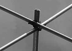
| Fig.3 |
| Building A Two Element Cubical Quad For Eleven Meters |
 |
| 1/4 wave 75 OHm cable |
| 3 or 4 windings through ferrite core ring |
| connecting plug > 50 OHm cable to TX |
| Fig.5 |
 |
| Fig.6a Wire Gamma Match used on the 3 ele quad. |
| approx. 42 cm |
| < 25 mm |
| See text for details of capacitor etc. |
 |
 |
 |
 |
| A three element cubical quad built using same construction method. |
| Fig. 3a Hardwood end spreader. |
| Fig. 2a |
| Fig. 7 |
| Fig.6 |
 |
 |
| A 2-element Cubical Quad using 16mm PVC tubing for spreaders. Cheap to build and ideal for portable use. |
| The boom: 30mm aluminium tubing is drilled both ends to fit the 12mm aluminium tubing or "studs" which holds the 16 mm PVC tubing. A 20 mm cut is made in the PVC and hose-clips lock it to the studs on the boom. Boom is approx 1700 mm X 30 mm aluminium tubing. Studs 1000 mm X 12 mm aluminium tubing ( 500mm to hold each spreader) 4 lengths required. PVC 2000 mm X 16 mm 8 lengths required. 8 hose-clips Resin glue to keep studs in place and strengthen ends of boom. Freq 27.300 Total element length 0ne side Spreader Spacing between Ref and Driver 164.7 cm for max gain (See: Results below) Driver 1122 cm 208.5 cm 198.35 cm Reflector 1149.9 cm 287.49 cm 203.2 cm Driver is tuned first for lowest VSWR before matching feed is attached. Antenna should be approx 3 meters above ground while adjusting VSWR. From feed-point on antenna, attach 50 Ohm coaxial cable with a choke ( 5 windings of cable with diam of approx 130mm bound with PVC tape ), one quarter wave from feed point. The impedance is low so the feed can be direct, or through a 1:1 balun, either way, there is very little variation. Reflector is kept approx 3 to 5 % larger than Driver (tuned to a lower freq) Apart from the wire, the total cost to build this antenna was about $US15 ..... RESULTS You only have to check out my reports in the "Archive Search" page on the www.cluster.dk after 20th March '02, to see the results of this very easy to build antenna. Before that date, I was using the 3 element quad pictured above. The above is just a rough guide. Even if you are not that precise with the measurements, the antenna will work very well .... main thing is to get the VSWR down to about 1.5:1. Note: With the maximum spacing.... the gain is probably less than 0.5dB and I would have prefered to have a shorter spacing which would have lowered the feed impedance closer to 50 OHms, and also have made the quad more broad-banded so that I could use it on the lower end of the 11 meter band. However, it works well between 26.600 kHz to 27. 650 kHz. The closer the spacing, the lower the feedpoint impedance. You can see how "flimsy" my antenna is! PVC tubing might not be the best material to use, but it is cheap and it works very well. At least 3 S points more than the 5/8 vertical. It is directional and cuts out a lot of the QRM and noise common to a vertical antenna. |
| PVC tubing is held to the 12 mm alum. tubing ( forming the spider section on boom ) with hose clips. |
| Now..... A very cheap and simple way to construct a 2 element quad using PVC spreaders. |