
1. INTRODUCTION
This is a preliminary report on a project to develop a device to store medicines and other
temperature sensitive materials at 'room temperature' while travelling and living in an RV. Such a device
would also be suitable for storing medicines in ambulances and emergency vehicles. The instructions for
most medicines, over the counter and prescription, recommend storage at 'room temperature' to assure
long-term effectiveness. Extreme temperatures can reduce the useful life of many medicines. Indeed,
temperatures inside RVs, ambulances, and emergency vehicles are often sufficiently high or low to
shorten the life of, or even destroy, medications. In my experience some medicines can quickly lose their
efficacy by exposure to temperatures higher than even 77 degrees F. The term 'room temperature' is
open to interpretation and is not consistent between medicines. It is apparent, however, that a
temperature range between 60 and 70 degrees F. falls within most, if not all, renditions of room
temperature. This view is supported by my local pharmacist.
Before starting this project I looked into purchasing a ready made ' room temperature' storage
unit to use in my RV. The few units that I found for sale were expensive. They were designed for general
cooling or heating to fairly precise temperatures, over a wide span of possible thermostat settings. In
addition to their high price, they did not have all of the features that I considered desirable, and which
became part of the design criteria for my project. The criteria include:
| - low cost |
| - reliability |
| - simple operation |
| - ability to keep contents within room temperature range with ambient temperatures reaching from freezing to 100 degrees F. |
| - a 'fail-safe' capability to warn of device malfunction |
| - capability to work from a vehicle 12 volt electrical system (even with the noisy, unstable DC electricity often found in an RV) |
| - relatively low power consumption |
| - light weight and suitably compact |
The method that I developed for storing medicines at room temperature appears to meet these
criteria. The project remains a work in progress, however. I have tested a prototype device on the
'bench', but I have yet to try it extensively in the field. I am hoping to do this during the forthcoming
winter while RVing (with extensive boondocking) in the Southern U.S.A. for a few months. In the end, I
would like to be able to report with confidence that the project is a success. If I do not fully succeed, at
least I will be able to relate the difficulties encountered and wish good luck to the next experimenter who
may be interested in making such a device.
The heart of my room temperature storage unit is a commercially available and inexpensive thermoelectric cooler/heater. Adapting the cooler/heater for this purpose has two facets.
Figure 1 |
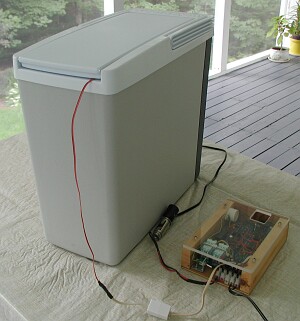 |
Figure 1 shows the prototype device consisting of a Koolatron Van model thermoelectric
cooler/heater and a temperature control unit that I constructed on a Vector board and housed in a wood and
plexiglass box. I selected this Koolatron model because of its compact size. The principles applied here
should work with other models and brands of thermoelectric cooler/heaters.
2. THE TEMPERATURE CONTROLLER
Commercially available thermoelectric cooler/heaters consist of an insulated container with a
thermoelectric (a.k.a. Peltier) heat transfer element assisted by a fan. Depending on the polarity of the DC
electricity to the element, the container will be either cooled or heated. The job of the temperature
controller is to turn on the cooling or heating mode respectively to ensure that temperatures within the
cooler/heater do not go higher nor below the room temperature range.
The controller is based on an analogue circuit of my design, and is built from commonly available,
inexpensive, and reliable components. The cooler/heater plugs into the controller. A temperature sensor
probe is located in the container and connects by wire to the controller device. The length of the wire and
location of the controller are not critical. When the temperature at the sensor goes above or below pre-set
levels the thermoelectric element is turned on, either cooling or heating as appropriate. Once on, heating
or cooling continues through an hysteresis of about 4.5 degrees F. before turning off. All parameters are
set by resistor values in the circuit.
Further, there is a fail safe feature. If the temperature in the cooler/heater apparently goes below
minimum or above maximum thresholds, perhaps indicating malfunction of the cooler/heater or controller
components (e.i. broken sensor wire), an alarm buzzer sounds continually and power to the
thermoelectric element is turned off until reset. A fail safe override switch deactivates the alarm buzzer
and allows for cooler/heater operation at temperatures below or above the thresholds. Deactivation
would be warranted, for example, when the cooler/heater is first turned on and time is needed for its
internal temperature to reach the desired range. If the internal temperature is within the fail safe limits,
toggling the override switch resets the fail safe condition and restores normal controller operation.
The prototype has the following 'electronic' temperature on/off and fail safe settings.
| NORMAL OPERATION | ON | OFF |
| Heating | 58.5 F. | 63.0 F. |
| Cooling | 70.2 F. | 65.6 F. |
| FAIL SAFE | LOW | HIGH |
| Turn off below/above | 54.2 F. | 74.4 F. |
These temperature settings were chosen for the prototype to be reasonably within a normal 'room
temperature' as may be required for the optimum storage of medicines. (Note, precise temperature
settings, e.g. 60 and 70 degrees, are difficult to achieve because standard resistors have only a limited
number of values, and manufacturing tolerances can result in values deviating by several percent.)
In practice, the imprecision of the sensor probe and the internal environment of the cooler/heater
causes the operational specifications to deviate somewhat from the electronic settings. Typical
measurements in the prototype, taken from a thermometer sensor nearby the controller's probe, are as
follows:
| ON | OFF | |
| Heating | 58.6 F. | 63.1 F. |
| Cooling | 68.2 F. | 64.6 F. |
There are five indicator lights (LEDs) that turn on when the controller is: i) connected to power,
ii) causing the cooler/heater to cool, iii) causing the cooler/heater to heat, iv) suspended by fail safe
mode, and v) operating with fail safe overridden.
3. MODIFYING THE COOLER/HEATER FOR UNIFORM INTERNAL TEMPERATURE
In commercially available thermoelectric cooler/heaters the thermoelectric element is usually located on a side wall or top of the container, which creates a nearby region of concentrated heating and cooling. The remainder of the container's space is heated and cooled by a combination of radiation, convection, and conduction (via the material of the container and its contents). This arrangement results
| Figure 2 |
 |
| Figure 3 |
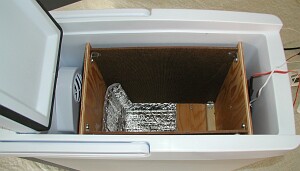 |
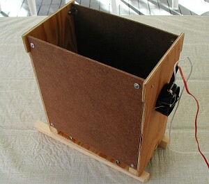
Figure 2 shows how the baffling mechanism was constructed for the prototype unit. Construction
is of 1/4 " plywood and 1/8" tempered hardboard, although other materials should be as effective. The
baffle incorporates selectively-placed insulation and a holder (black cup) for the temperature sensing
probe. The installation of the baffle in the cooler/heater is depicted in figure 3.
Proper placement of insulation in and around the baffle was found to be important. This was
highlighted during temperature testing in cold ambient temperatures when it became apparent that there
were significant temperature variations inside the baffled container. In particular, the radiant effect of the
thermoelectric unit when heating caused the adjacent internal temperature in the baffled container to rise
significantly above other locations. A small patch of insulation inside the container near the 'hot spot' and
across the top seemed to provide adequate protection when the thermoelectric unit was cooling but was
evidently inadequate when heating. Two more thermometers were employed to the test setup to measure
temperature variations in the storage area. One thermometer was located in the area closest to the
thermoelectric unit (where temperatures would be hottest while heating and coldest while cooling), and
the other was farthest away at the top corner. The 'hot spot' problem was solved by reorienting and
adding insulation to the outside bottom of the baffle. Before and after operational measurements are as follows:
| OUTSIDE
TEMPERATURE (APPROX. DEG.F.) |
LOCATION OF THERMOMETER |
TEMPERATURE INSIDE
CONTAINER DURING TEST PERIOD (DEG. F.) | |
| MINIMUM | MAXIMUM | ||
| BEFORE MODIFYING INSULATION: | |||
| 35 | Sensor | 59.4 | 63.9 |
| 'Hot Spot' | 62.1 | 80.4 | |
| Far Corner | 61.2 | 68.2 | |
| AFTER MODIFYING INSULATION: | |||
| 30 | Sensor | 59.4 | 64.2 |
| 'Hot Spot' | 62.6 | 64.2 | |
| Far Corner | 59.7 | 61.3 | |
| 32 | Sensor | 59.2 | 63.9 |
| 'Hot Spot' | 55.4 | 61.3 | |
| Far Corner | 56.1 | 59.5 | |
| 36 | Sensor | 59.7 | 63.5 |
| 'Hot Spot' | 63.1 | 64.2 | |
| Far Corner | 61.0 | 65.3 | |
5. POWER UTILIZATION
The cooler/heater and controller operate at a nominal 12 volts DC, but can withstand modestly
higher voltages and continue to function at modestly lower voltages. The operating range for the
prototype controller is approximately 10.5 to 16 volts. (The prototype system has operated successfully
when powered by a ferro-electric AC-DC converter that is commonly used in recreation vehicles. Such
converters are notorious for their unstable and noisy DC power output.)
At 13.1 volts (from a regulated power supply) the current draw of the prototype is as follows:
MODE |
CONTROLLER ONLY |
CONTROLLER AND COOLER/HEATER * |
| Idle (cooler/heater temperature within 'room' range) |
32 ma | 32 ma (cooler/heater off) |
| Cooling | 105 ma | 3.58 amps |
| Heating | 105 ma | 3.63 amps |
| Fail Safe Set | 98 ma | 98 ma (cooler/heater off) |
| FAIL SAFE OVERRIDE: |
||
| - Cooling | 114 ma | 3.58 amps |
| - Heating | 117 ma | 3.63 amps |
- * the cooler/heater in the prototype draws approximately 3.47 amps while cooling and 3.52 amps while heating.
The electricity current requirements of the controller are relatively small. At idle the 32 ma current
draw represents only 0.75 amp hour of electricity use in a 24 hr. period. When the cooler/heater is on
(normal or fail safe override), the controller adds about only 3% to the total current draw of the
prototype system. Electricity utilization of the cooler/heater depends on the capacity of the model used.
The prototype controller has components that allow a cooler/heater to draw up to 12 amps. This could be
extended further by the substitution of two components in the controller circuit.
Limited testing of the system suggests an on-time duty cycle of the prototype as follows for
various outside temperatures. The lower the duty cycle, the less electricity would be used by the system
in a time period for any given outside temperature. The farther that the outside temperature deviates from
the 'room temperature' parameters of the controller the greater will be the duty cycle.
| OUTSIDE
TEMPERATURE RANGE (DEG. F.) |
APPROX. TIME PERIOD |
ON TIME |
DUTY CYCLE |
HEATING: |
|||
| 88 -90 | 1 hr. | 0.62 hrs. | 53 % |
| 80 - 86 | 2 hrs. | 0.61 hrs. | 31 % |
| 70 - 80 | 4 hrs. | 0.80 hrs.. | 20 % |
| 68 - 88 | 11 hrs. | 2.58 hrs | 23 % |
| 71 | 2 hrs. | 0.18 hrs. | 9 % |
| COOLING: | |||
| 56 -54 | 9 hrs. | 0.75 hrs. | 8 % |
| 30 | 1 hrs. | 1 hr. est.* | 50% est.* |
- * duty cycle based on observations during a longer test period where the duty cycle clock eventually stopped working because of the cold.
These measurements are approximate and do not cover a full range of possible outside temperatures. They indicate, however, that even in relatively hot and cold environments the cooler/heater can sustain an interior room temperature for storage while being on for one-half or less of the time. It is noted that a cooler/heater with superior thermal insulation than that of the prototype would likely be more effective in retaining internal temperatures, resulting in a significantly reduced duty cycle.